
CMP Pad Dresser with Oriented Particles and Associated Methods

a technology of oriented particles and dressing racks, which is applied in the field of oriented particle dressing racks and associated methods, can solve the problems of increasing the wear rate of superabrasive particles and the polishing rate, and achieve the optimization of enhance and optimize the dressing rate and dresser wear

Active Publication Date: 2009-07-23
KINIK
View PDF30 Cites 2 Cited by
  • Summary
  • Abstract
  • Description
  • Claims
  • Application Information

AI Technical Summary

Benefits of technology

[0009]Accordingly, in one aspect, the present invention provides methods and CMP pad dresser configurations for controlling CMP pad dresser performance. In one such method, a CMP pad dresser is provided which employs a plurality of superabrasive particles each coupled to a substrate member and oriented into an attitude that provides anticipated performance characteristic as part of the CMP pad dresser fabrication performance. In other aspects, the performance characteristic of the present invention can optimize dressing rate and dresser wear. Furthermore, in another aspect of the present invention, the performance characteristic can be an optimized balance of dressing rate and dresser wear. It has been discovered that orienting the superabrasive particles in a predetermined pattern or configuration can enhance and optimize the dressing rate and dresser wear. More particularly, a method that employs superabrasive particles to have a predetermined attitude can control the dresser performance characteristics.
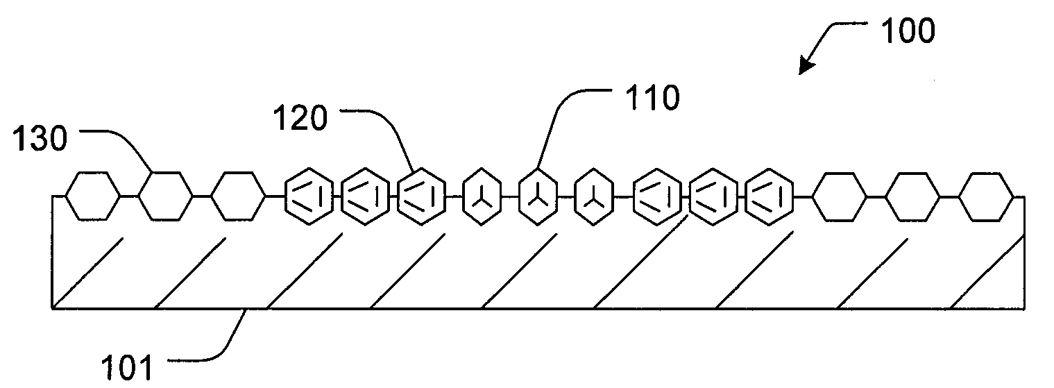
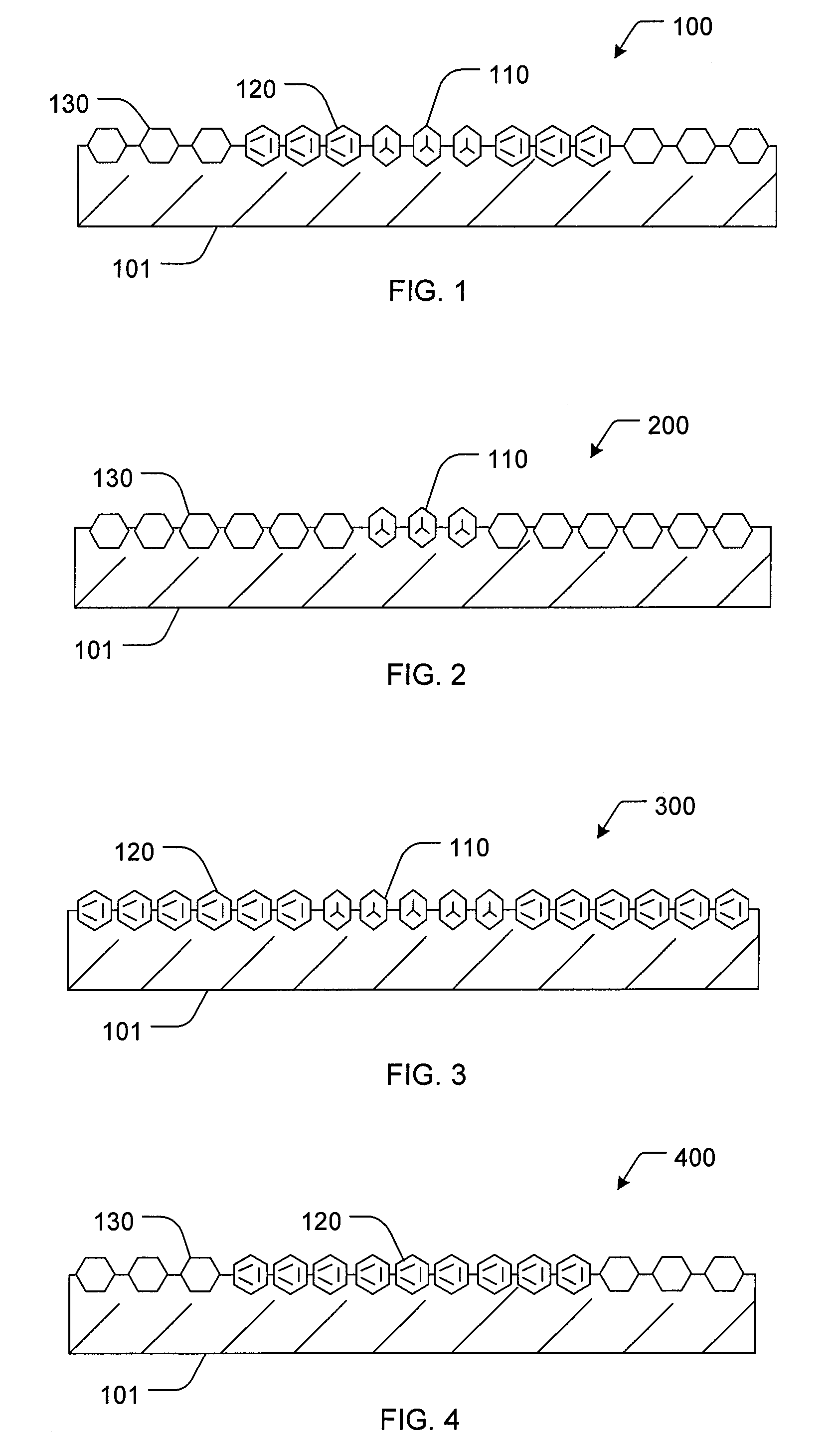
[0011]In an another aspect, superabrasive particles in a central location can be oriented in an attitude having an apex portion oriented toward a pad to be dressed and superabrasive particles in a peripheral location can be disposed on the substrate or surface in an attitude having either a face or an edge portion oriented toward a pad to be dressed. Varied orientations can create various asperity patterns in the CMP pad. Such patterns can provide variability in the dresser performance by providing asperities that increase the wafer polishing rate while reducing the particle wear. For example, in one aspect, the dresser rate and dresser wear can be balanced by configuring the attitude of centrally located particles to be an apex, the attitude of the peripherally located particles to be a face and any particles therebetween to have an attitude of an edge oriented towards a pad to be dressed.
[0012]In yet another aspect of the present invention, a method for optimizing dresser performance may include providing a CMP pad dresser having a plurality of superabrasive particles centrally located which are of a lower quality than peripherally located superabrasive particles. The lower quality can be a number of characteristics such as, lower internal quality, lower shape quality, etc. It has been found that particles of lower shape quality, such as irregular shapes, can dress a CMP pad more aggressively than those of higher shape quality, however, the lower quality particles have a slower pad dressing rate because they are prone to chipping and breaking. On the other hand, the higher shape qualities, such as octahedral or cubo-octahedral, dress less aggressively, however, have more durability, allowing for a higher dressing rate. The durability also helps shield the inner or central particles from excessive wear. Therefore, placing a lower quality particle in the central location of the pad dresser and a higher quality particle on the peripheral, can result in a balanced dressing rate and dresser wear.
[0013]In addition to the above-recited methods of use, the present invention also includes methods for producing a CMP pad dresser that optimizes dresser performance by orienting the superabrasive particles in a predetermined pattern. Generally speaking, such a method may include providing a substrate, selecting an attitude for superabrasive particles that provides an anticipated performance characteristic, orienting the superabrasive particles in an attitude in relation to the substrate, and bonding the superabrasive particles to the substrate in the selected attitude.
[0014]Using the methods described above, CMP pad dressers exhibiting considerable advantages may be created. For example, the CMP pad dressing performance can be controlled to optimize CMP pad dressing rate and dresser wear. Such optimized performance can create a balance between dresser wear and dressing rate, thus lengthening the service life of the dresser, while maximizing the rate at which the dresser grooms the pad.

Problems solved by technology

However, the increased polishing rate may also increase the wear rate of the superabrasive particles.

Method used


Image

  • CMP Pad Dresser with Oriented Particles and Associated Methods
  • CMP Pad Dresser with Oriented Particles and Associated Methods

Examples


Embodiment Construction

[0020]Before the present CMP pad dresser and accompanying methods of use and manufacture are disclosed and described, it is to be understood that this invention is not limited to the particular process steps and materials disclosed herein, but is extended to equivalents thereof as would be recognized by those ordinarily skilled in the relevant arts. It should also be understood that terminology employed herein is used for the purpose of describing particular embodiments only and is not intended to be limiting.

[0021]It must be noted that, as used in this specification and the appended claims, the singular forms “a,” and, “the” include plural referents unless the context clearly dictates otherwise. Thus, for example, reference to an “abrasive particle” or a “grit” includes reference to one or more of such abrasive particles or grits.

DEFINITIONS

[0022]In describing and claiming the present invention, the following terminology will be used in accordance with the definitions set forth bel...


PUM


Abstract

CMP pad dressers with superabrasive particles oriented into an attitude that controls CMP pad performance, and methods associated therewith are disclosed and described. The controlled CMP pad performance may be selected to optimize CMP pad dressing rate and dresser wear.

Description

RELATED APPLICATIONS[0001]This application is a continuation of U.S. patent application Ser. No. 11 / 238,819, filed on Sep. 28, 2005, which claims the benefit of U.S. Provisional Patent Application No. 60 / 614,596 filed Sep. 28, 2004, each of which are incorporated herein by reference.FIELD OF THE INVENTION[0002]The present invention relates generally to devices and methods for use in connection with dressing or conditioning a chemical mechanical polishing (CMP) pad. Accordingly, the present invention involves the chemical and material science fields.BACKGROUND OF THE INVENTION[0003]Chemical mechanical process (CMP) has become a widely used technique for polishing certain work pieces. Particularly, the computer manufacturing industry has begun to rely heavily on CMP processes for polishing wafers of ceramics, silicon, glass, quartz, metals, and mixtures thereof for use in semiconductor fabrication. Such polishing processes generally entail applying the wafer against a rotating pad mad...

Claims


Application Information

Patent Timeline
Patent Type & Authority Applications(United States)
IPC IPC(8): B24B53/12B24B1/00B24B53/02B24D18/00
CPCB24B53/017B24D18/00B24B53/12B24B53/02H01L21/304
Inventor SUNG, CHIEN-MIN
Owner KINIK
Learn More