Method for Channel Calibration

Inactive Publication Date: 2009-07-23
APPLE INC
View PDF6 Cites 21 Cited by
  • Summary
  • Abstract
  • Description
  • Claims
  • Application Information

AI Technical Summary

Benefits of technology

[0030]The first terminal may be a base station and the second terminal may be a mobile terminal. In this instance, the mobile terminal velocity may be determined to see if it is below a threshold value in order to prevent

Problems solved by technology

This results in extra expense when building networks and also additional complexity in the terminals.
Furthermore, if tower top amplifiers or other non-reciprocal tow

Method used


Image

  • Method for Channel Calibration
  • Method for Channel Calibration
  • Method for Channel Calibration

Examples


Example

[0038]The present invention will be discussed with reference to a cellular communications system including base stations and mobile terminals. However, it may be implemented between any two terminals that are connected by wireless communication channels.

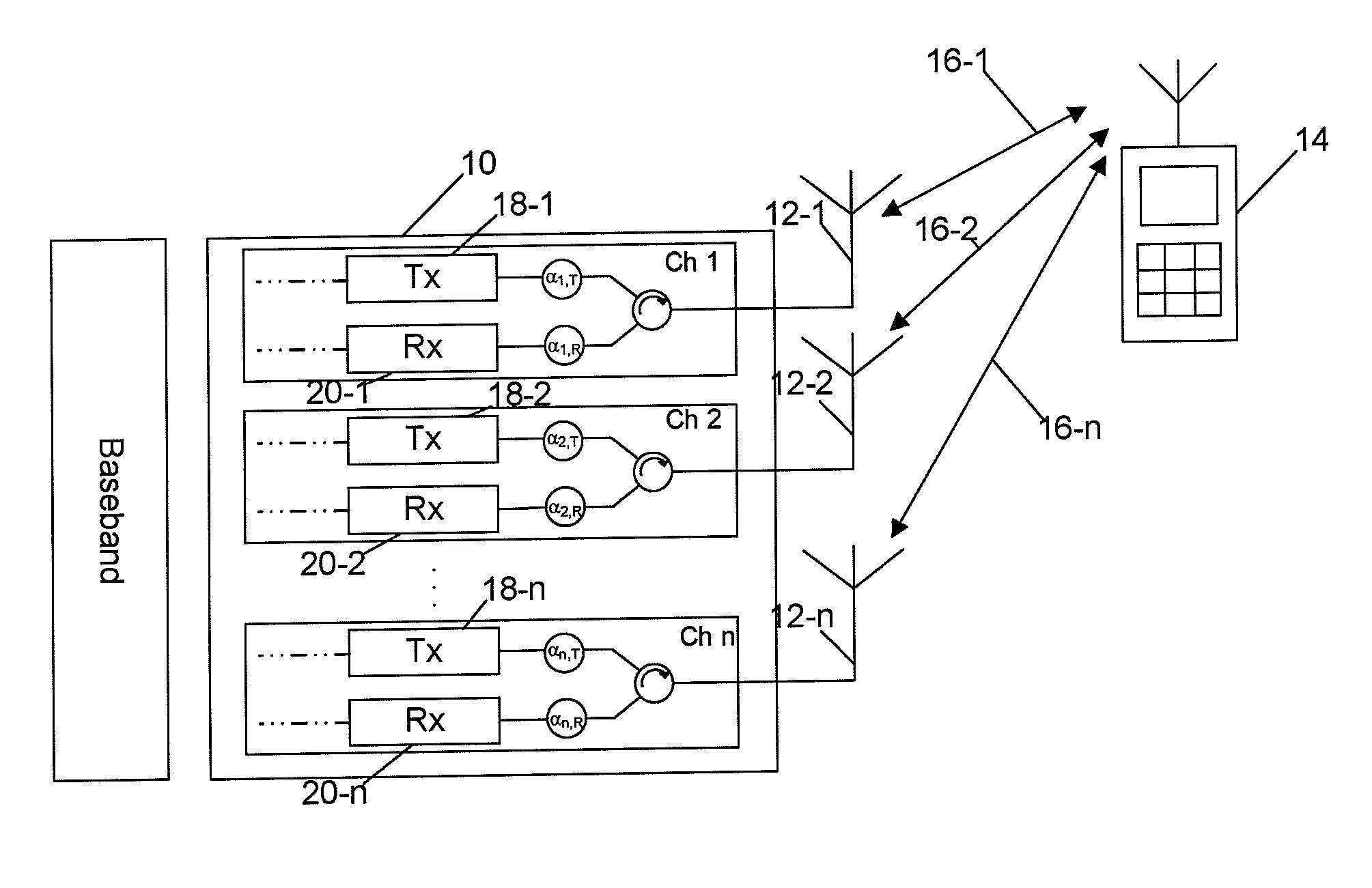
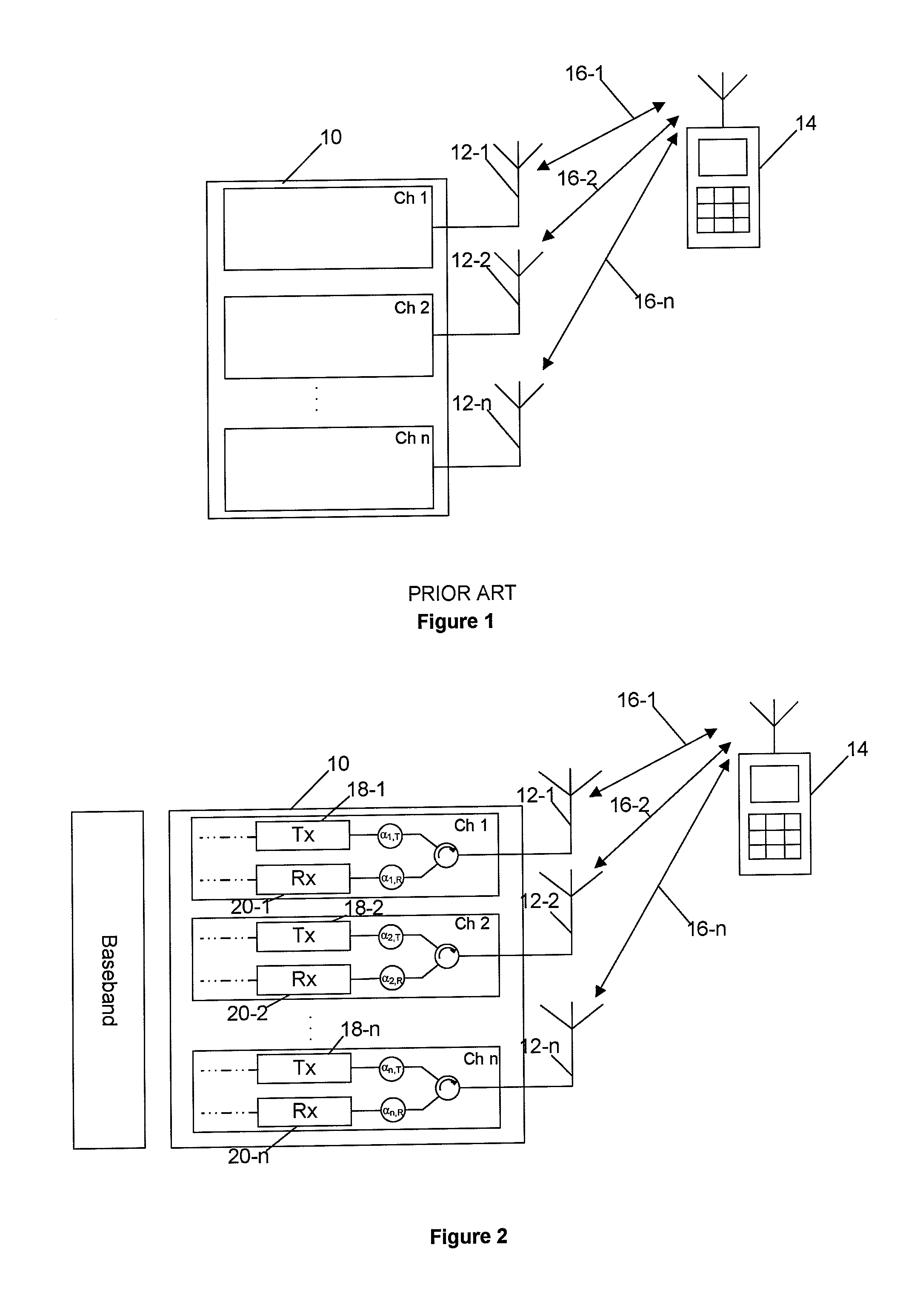
[0039]FIG. 2 illustrates the apparatus of the present invention. As in conventional wireless cellular communications systems there is a base station 10 having n antennas 12-1, 12-2 . . . 12-n. Each antenna 12-1, 12-2 . . . 12-n is connected to a transmission circuit 18-1, 18-2 . . . 18-n and a receiver circuit 20-1, 20-2 . . . 20-n.

[0040]The transmission circuit is responsible for processing the signals prior to them being transmitted by the antenna and the receiver circuit is responsible for processing the signals that are received by the antenna. Each circuit introduces particular complex frequency dependent factors that vary according to the circuit and radio channel being used. The introduced factors are denoted in FIG. 2 as αC,...


PUM


Abstract

The present invention provides an improved method for calibrating transmitter and receiver circuits in a device having multiple antennas. The method involves transmitting pilot signals from the device to a second device and from the second device to the device. Each device determines the relative differences between the signals received by a first antenna and by each of the other antennas. The relative differences can then be used to calculate calibration factors that can be applied to the transmitter and receiver circuits.

Description

FIELD OF THE INVENTION[0001]This invention relates to a method of calibrating a device having multiple antennas. The invention is applicable to use within base stations of a cellular telecommunications network.BACKGROUND OF THE INVENTION[0002]In communications systems, such as a cellular communication system, it is advantageous to use multiple transmitters and receivers to exchange data wirelessly between two terminals. The use of multiple transmitters and receivers results in an improved performance with, for example, increased transmission range, an improved signal to noise ratio, interference rejection for received signals and a reduced power requirement for transmitted signals.[0003]In a known multiple antenna arrangement, such as that illustrated in FIG. 1 and used in a cellular communication system, a base station 10 is provided with multiple antennas 12-1, 12-2, 12-n, arranged to both transmit and receive data to mobile terminals such as a cellular telephone 14. When the base...

Claims


Application Information

Patent Timeline
IPC IPC(8): H04B1/06
CPCH04B7/04H04B17/20H04B17/12H04W24/06H04L5/0048H04W88/10H04B17/21
Inventor GALE, SIMON
Owner APPLE INC
Why Eureka
Try Eureka