
Joint Arthroplasty Kit and Method

a joint arthroplasty and kit technology, applied in the field of orthopaedics, can solve the problems of large variation in the amount of void in the bone under the prosthesis, affecting the function of the prosthesis, and the flattening of the humeral head

Inactive Publication Date: 2009-07-23
DEPUY PROD INC
View PDF77 Cites 164 Cited by
  • Summary
  • Abstract
  • Description
  • Claims
  • Application Information

AI Technical Summary

Benefits of technology

"The present invention provides a tool for accurately measuring the contour of a long bone, such as a humerus, for joint replacement surgery. The tool includes a body with a contact face for the prosthesis and a probe that can be used to determine the appropriateness of a particular sized surface replacement prosthesis. The tool can also be used to determine the required thickness of augmentation spacers for filling the missing bone. Additionally, the tool can be used to determine the placement of a guide rod for fitting a prosthesis. The technical effects of the invention include accurate measurement of the void in the bone and improved accuracy in joint replacement surgery."

Problems solved by technology

However, the current trend is to use the cements to a lesser extent because of their tendency to lose adhesive properties over time and the possibility that cement contributes to wear debris within a joint.
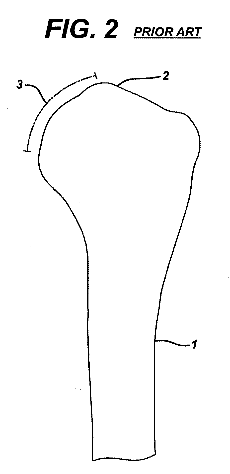
Typically, however, arthritis of the gleno-humeral joint causes flattening of the humeral head with a large medial osteophyte.
The flat humeral head can cause voids in the bone under the prosthesis resulting in limited contact between the prosthesis and the resected bone and may limit the load transfer capability between the prosthesis and the humerus.
Great variations in the size of a patient's humerus and the humeral head of that humerus, as well as variations in the progress of the arthritis or other disease that leads to the flattening of the humeral head results in a large variation in the amount of void in the bone under the prosthesis.
Determining the amount of void in the humeral head is, therefore, important but yet, difficult to determine.
Such x-rays, however, only portray the broad outline of the humerus and may not accurately show the shape of the defect.

Method used


Image

  • Joint Arthroplasty Kit and Method
  • Joint Arthroplasty Kit and Method
  • Joint Arthroplasty Kit and Method

Examples


Embodiment Construction

[0054]Embodiments of the present invention and the advantages thereof are best understood by referring to the following descriptions and drawings, wherein like numerals are used for like and corresponding parts of the drawings.

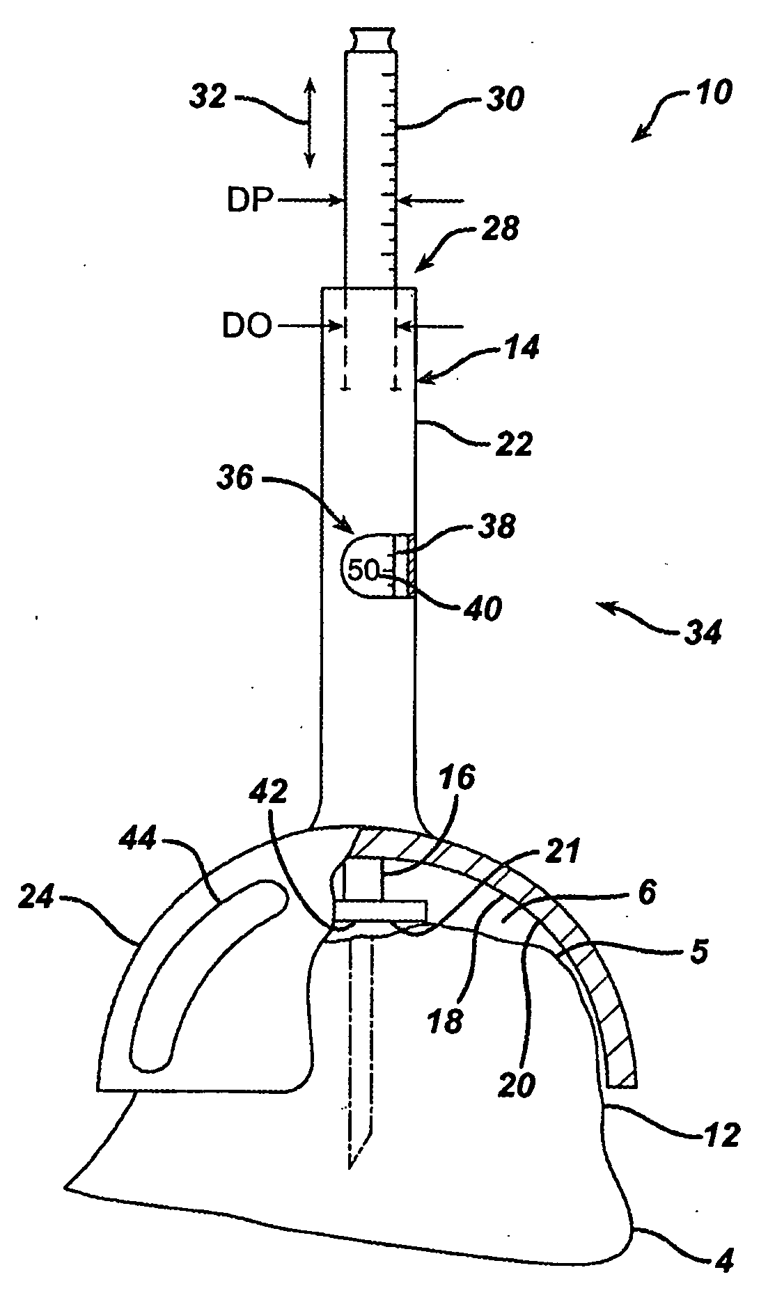
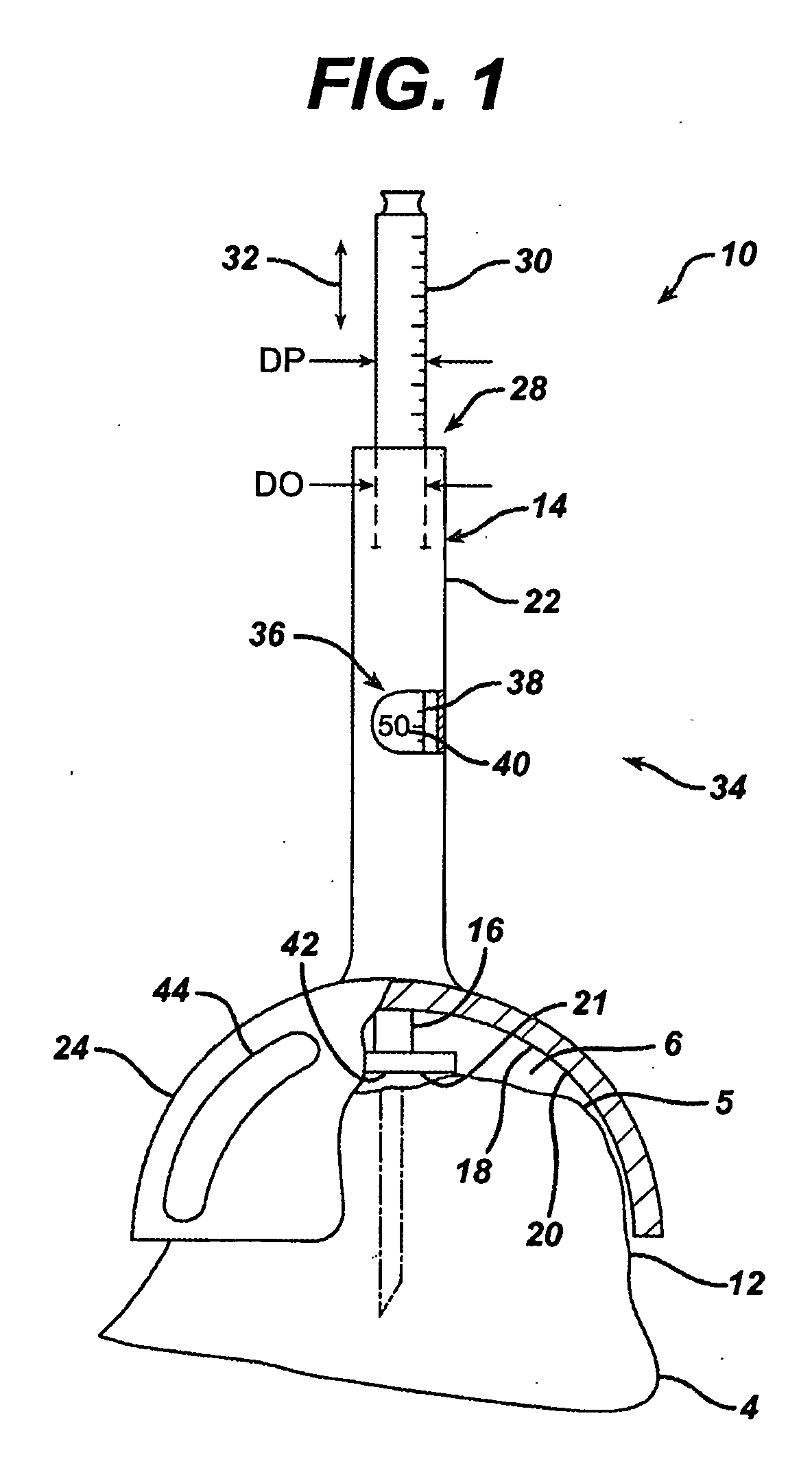
[0055]According to the present invention and referring to FIG. 1, gauge 10 is shown. The gauge 10 is used for measuring bone contour 12 of the bone 4, for example, a humerus, for use in joint arthroplasty. The gauge 10 includes a body 14 and a probe 16. The body 14 has a portion 18 of the body 14 for contact with the bone 4. The probe 16 is movably positional with respect to the body 14. The probe 16 includes a contact portion 21 of the probe 16 for contact with the bone 4. The relative position of the probe 16 with respect to the body 14 is indicative of the bone contour 12 of the bone 4.

[0056]The gauge 10 may, as shown in FIG. 1, be such that at least a portion of the portion 18 for contact with the bone 4 includes a contoured portion with a periphery 20 sim...


PUM


Abstract

A method for providing joint arthroplasty includes providing a gauge for making a measurement of the contour of a long bone, making a measurement of the contour of a long bone with the gauge, providing a plurality of joint prostheses, selecting one of the plurality of joint prostheses based upon the measurement of the contour, resecting a long bone, and implanting the selected one prosthesis onto the long bone. A kit is also provided for selecting one of a plurality of joint implants for use in joint arthroplasty on a bone. The kit includes a first gauge and a second gauge.

Description

CROSS-REFERENCE TO RELATED APPLICATIONS[0001]This is a divisional application of U.S. patent application Ser. No. 10 / 403707 entitled “JOINT ARTHROPLASTY AND METHOD”. Cross reference is also made to the following applications: U.S. patent application Ser. No. 10 / 403750 entitled “ARTICULATING SURFACE REPLACEMENT PROSTHESIS”, U.S. patent application Ser. No. 10 / 403710 entitled “ARTHROPLASTY INSTRUMENT AND ASSOCIATED METHOD”, U.S. patent application Ser. No. 10 / 403364 entitled “EXTENDED ARTICULATION ORTHOPAEDIC IMPLANT AND ASSOCIATED METHOD”, U.S. patent application Ser. No. 10 / 794628 entitled “PUNCH, IMPLANT, AND ASSOCIATED METHOD” and U.S. patent application Ser. No. 10 / 403707 entitled “ARTHROPLASTY SIZING GAUGE”.TECHNICAL FIELD OF THE INVENTION[0002]The present invention relates generally to the field of orthopaedics, and more particularly, to an implant for use in arthroplasty.BACKGROUND OF THE INVENTION[0003]The invention relates to implantable articles and methods for implanting s...

Claims


Application Information

Patent Timeline
Patent Type & Authority Applications(United States)
IPC IPC(8): A61F5/00A61B17/58A61F2/30A61B19/00
CPCA61B2019/461A61B19/46A61B90/06A61B2090/061
Inventor MARONEY, BRIAN J.LONG, JACK F.IANNOTTI, JOSEPH P.WILLIAMS, JR., GERALD R.
Owner DEPUY PROD INC
Learn More