Apparatus and Method for Detecting a Rotation

Active Publication Date: 2009-07-30
INFINEON TECH AG
View PDF11 Cites 14 Cited by
  • Summary
  • Abstract
  • Description
  • Claims
  • Application Information

AI Technical Summary

Benefits of technology

[0011]An advantage of embodiments of the present invention is that the sensitivity of a rotation sensor is highly increased.

Problems solved by technology

Major problems occur in gyroscopes due to the so-called quadrature errors; these errors are related to non-ideal drive motion or driving force coupling energy into the sense or detection direction.
As the Coriolis force results in a displacement, which is, in general, by a factor of 10,000 smaller than the driven motion, the construction of MEMS gyroscopes is challenging and the electronic circuitry to operate the device is complex.
Conventional MEMS gyroscopes are too expensive for true volume applications while they do not have the necessitated degree of accuracy needed in specific applications, e.g., in navigation systems.
The first approach (a) is disadvantageous in that also the size of the overall device needs to be increased.
Further, manufacturing such a device becomes difficult.
The second approach (b) is not possible with MEMS gyroscopes since these devices work best at 10 kHz.
The third approach (c) is rather limited with MEMS gyroscopes as the suspension structures, like springs, and the driving force generating structures, like comb drives, do not allow a displacement exceeding ±5 μm.
The fourth approach (d) is limited by the above mentioned quadrature error and the noise limit of the amplifiers used in the detection circuitry.

Method used


Image

  • Apparatus and Method for Detecting a Rotation
  • Apparatus and Method for Detecting a Rotation
  • Apparatus and Method for Detecting a Rotation

Examples


Embodiment Construction

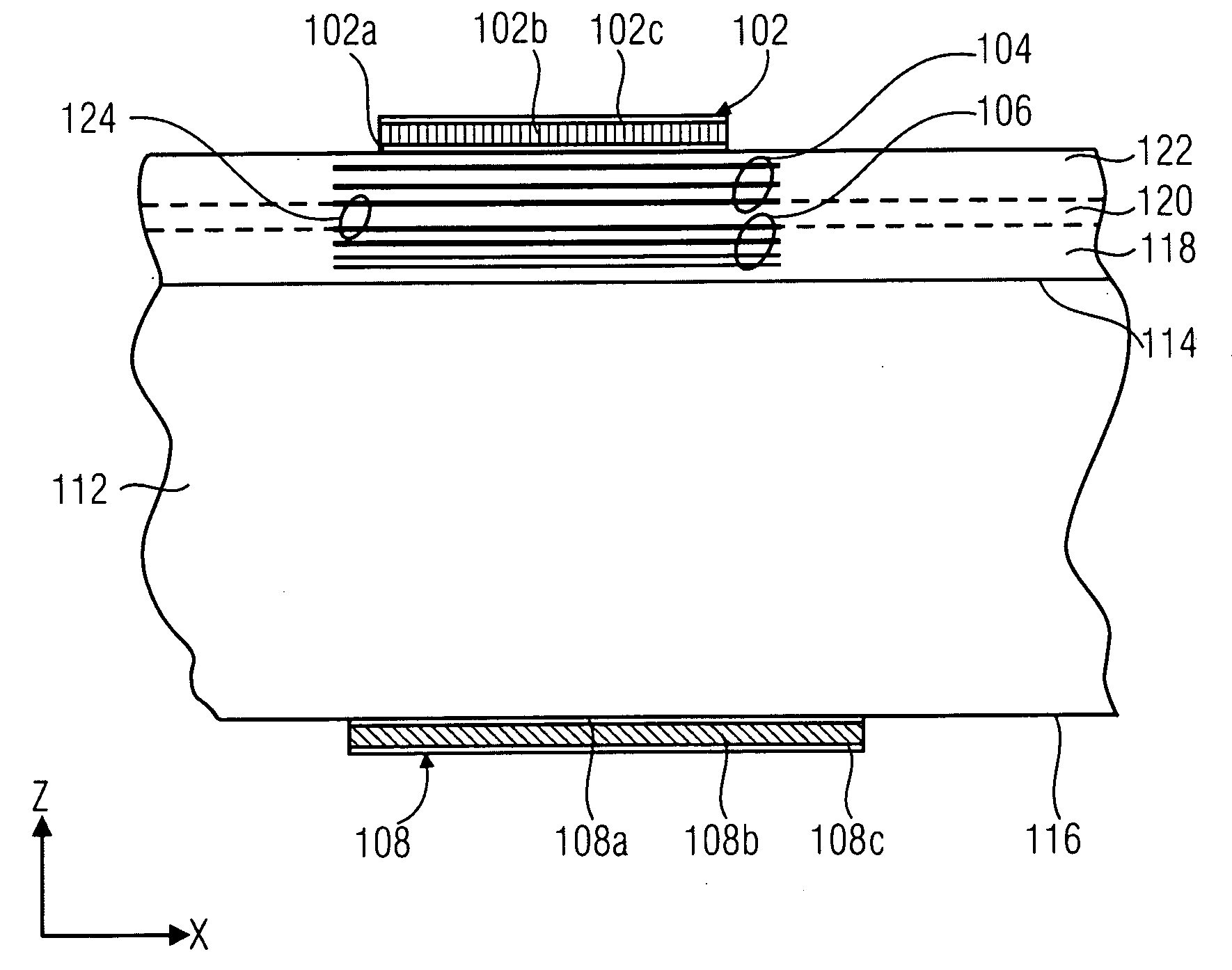
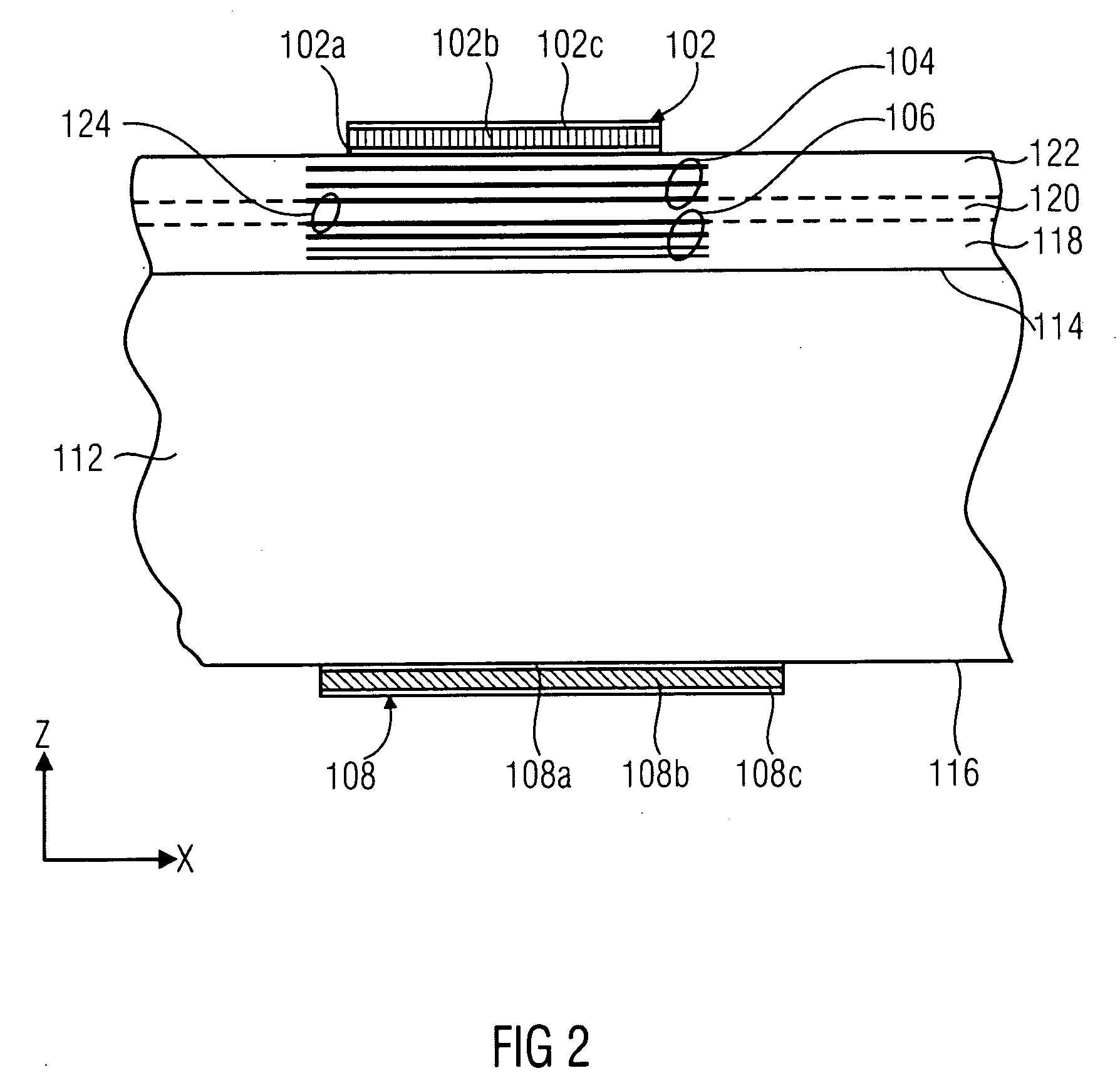
[0025]In accordance with embodiments of the present invention a rotation sensor is provided having a sensitivity which is highly increased when compared to conventional MEMS rotation sensors. This increase in sensitivity is achieved by a dramatic increase of the vibration frequency. This increase is possible by using a bulk-acoustic-wave device (bulk-acoustic-wave=BAW), which yields an increase in the frequency by a factor of 106 in comparison to conventional MEMS gyroscopes. Instead of a vibration frequency of 10 kHz typically used in MEMS gyroscopes, this approach allows vibration frequencies up to 10 GHz. While a BAW based rotation sensor shows considerably smaller vibration amplitudes when compared to conventional devices, e.g., 5 nm with BAW based devices instead of 5 μm of conventional devices (by a factor of 103 smaller), the gain in sensitivity is still a factor of about 1,000. Conventional MEMS devices will not work at 10 GHz at all, but BAW devices will operate at such a f...


PUM


Abstract

A rotation sensor has a substrate with a first surface and a second surface. A shear-wave transparent mirror is arranged on the first surface of the substrate, and a shear-wave isolator is arranged above the shear-wave transparent mirror, the shear-wave transparent mirror and the shear-wave isolator being arranged separated from each other to define a Coriolis zone there between. A bulk-acoustic-wave resonator is arranged above the shear-wave isolator, and a shear-wave detector is arranged on the substrate in a direction, in which a shear-wave generated by the bulk-acoustic-wave resonator upon rotation propagates.

Description

[0001]This application is a continuation of co-pending International Application No. PCT / EP2007 / 003908, filed May 3, 2007, which designated the United States and was published in English, and which claims the benefit of U.S. Provisional Application No. 60 / 818,235, filed Jun. 30, 2006, both of which applications are incorporated herein by reference.BACKGROUND[0002]The present invention concerns an apparatus and a method for detecting a rotation, especially an apparatus and a method for detecting a rotation on the basis of bulk acoustic waves.[0003]Conventional approaches for detecting a rotation about an axis use gyroscopes, e.g., MEMS gyroscopes (MEMS=micro-electromechanical system). Conventional MEMS gyroscopes are complicated vibrating micro-structures manufactured by surface-micromachining processes. Gyroscopes are based on measuring the Coriolis force. The Coriolis force is a small force perpendicular to both the velocity vector of a mass and the rotation axis. In a vibratory gy...

Claims


Application Information

Patent Timeline
IPC IPC(8): G01P3/00
CPCG01C19/5698
Inventor AIGNER, ROBERT
Owner INFINEON TECH AG
Why Eureka
Try Eureka