
Bicycle control device

a control device and bicycle technology, applied in the direction of bicycle brakes, axle suspensions, cycle equipment, etc., can solve problems such as unintentional operation by riders during normal riding conditions

Inactive Publication Date: 2009-07-30
SHIMANO INC
View PDF31 Cites 19 Cited by
  • Summary
  • Abstract
  • Description
  • Claims
  • Application Information

AI Technical Summary

Benefits of technology

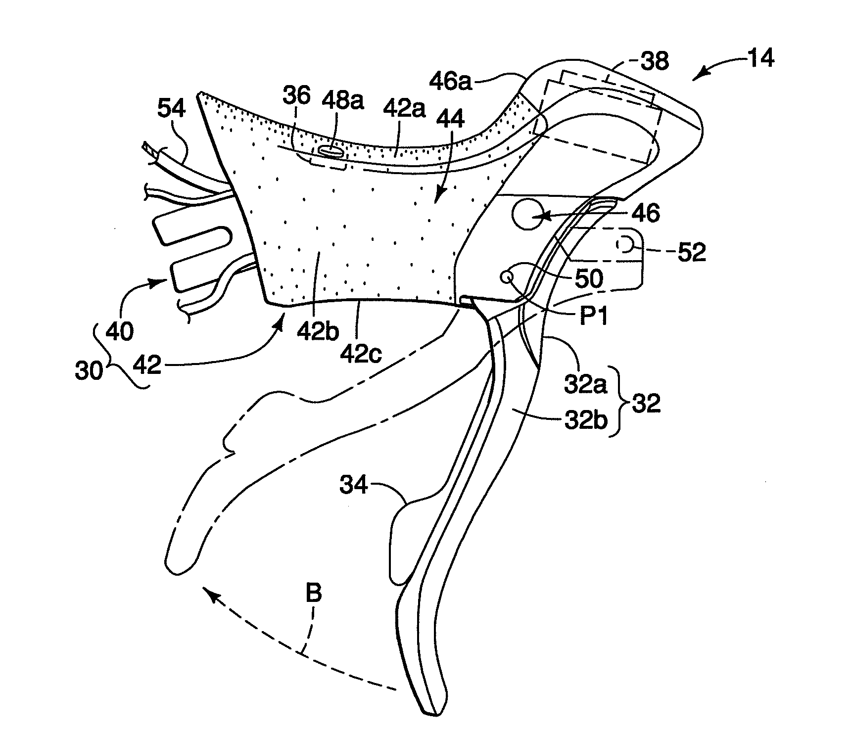
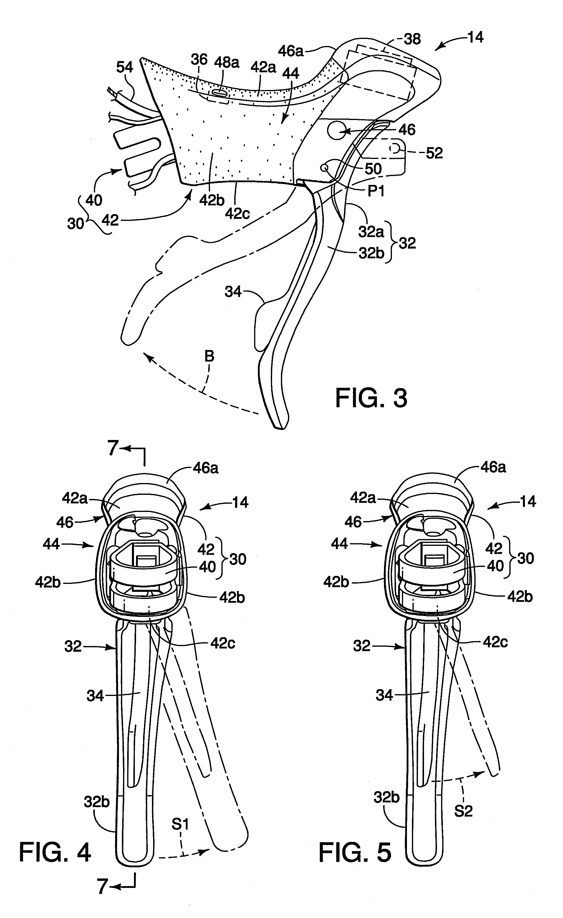
[0008]One object of the present invention is to provide a bicycle control device with an auxiliary electrical switch that can be used to operate an infrequently operated electrical device, but which is located in an area that avoids unintentional operation by the rider during normal riding conditions.

Problems solved by technology

However, many locations on the bicycle control device that are convenient to operate the switch are also locations that may result in unintentional operation by the rider during normal riding conditions.

Method used


Image

  • Bicycle control device
  • Bicycle control device
  • Bicycle control device

Examples


Embodiment Construction

[0027]Selected embodiments of the present invention will now be explained with reference to the drawings. It will be apparent to those skilled in the art from this disclosure that the following descriptions of the embodiments of the present invention are provided for illustration only and not for the purpose of limiting the invention as defined by the appended claims and their equivalents.

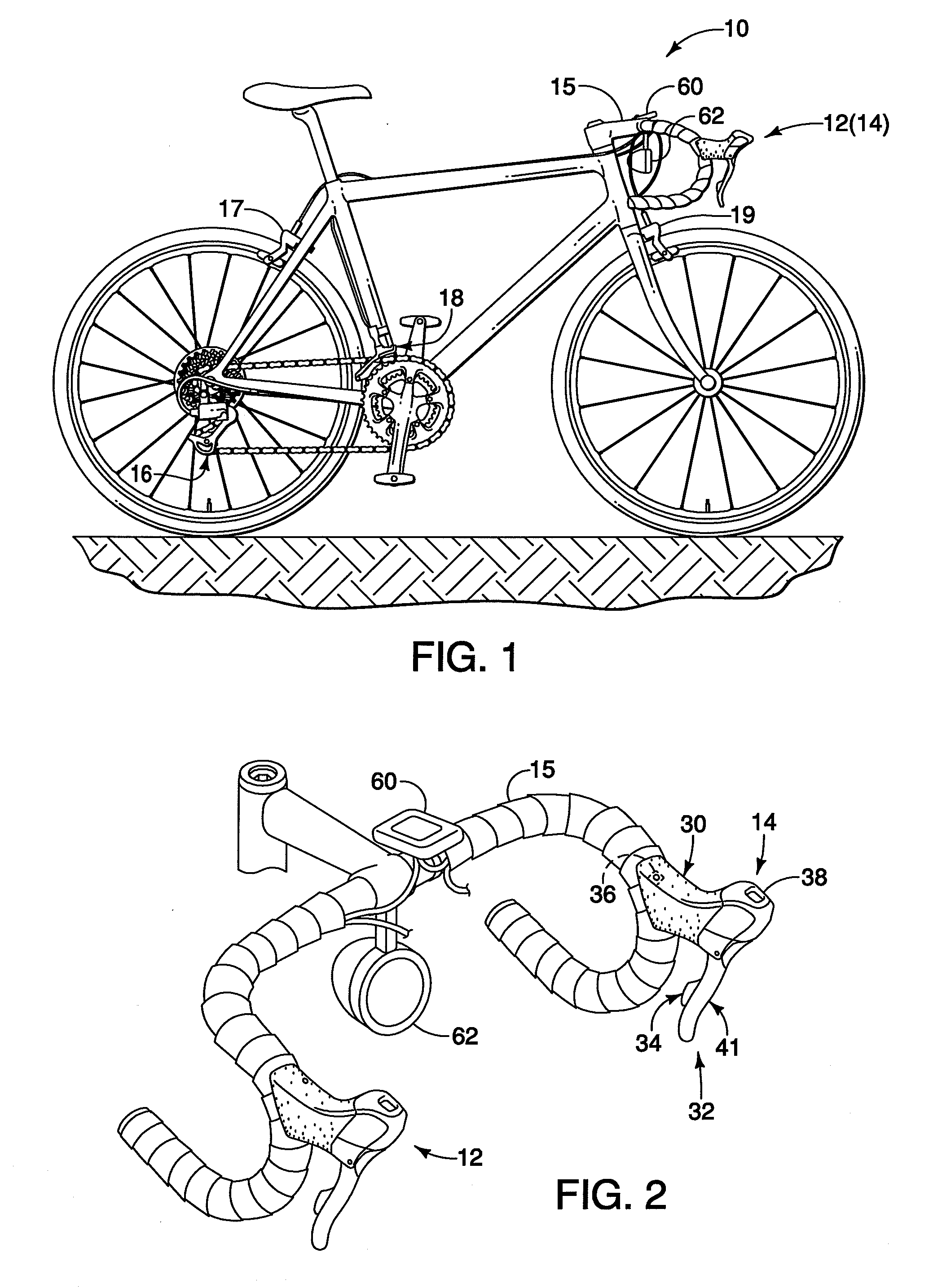
[0028]Referring initially to FIGS. 1 and 2, a bicycle 10 is illustrated with a pair of bicycle control devices 12 and 14 mounted on a drop down handlebar 15 in accordance with a first embodiment. In this first embodiment, the bicycle control devices 12 and 14 are brake / shift control devices which combine an electrical shifter with a brake lever. These types of bicycle control devices 12 and 14 are now commonly referred to as brifters, for their ability to combine the brake and shift functions into a single unit for use with one hand. The bicycle control devices 12 and 14 are road brifters that are ...


PUM


Abstract

A bicycle control device is basically provided with a bracket member, a brake lever and a non-shifting control switch. The bracket member has a handlebar mounting part and a main body with an upper surface, a pair of side surfaces and a lower surface, the main body being configured to form a gripping part. The brake lever is pivotally coupled to the main body of the bracket member at a coupling point such that the brake lever extends from the coupling point in a direction opposite of the upper surface with a majority of the brake lever being disposed below the handlebar mounting part. The non-shifting control switch is disposed on the main body of the bracket member in an area of the upper surface of the main body.

Description

BACKGROUND OF THE INVENTION[0001]1. Field of the Invention[0002]This invention generally relates to control devices for bicycles. More specifically, the present invention relates to control devices for bicycles that include at least one non-shifting control switch.[0003]2. Background Information[0004]Bicycling is becoming an increasingly more popular form of recreation as well as a means of transportation. Moreover, bicycling has become a very popular competitive sport for both amateurs and professionals. Whether the bicycle is used for recreation, transportation or competition, the bicycle industry is constantly improving the various components of the bicycle.[0005]Recently, bicycles have been equipped with a cycle computer for displaying riding conditions (bicycle speed, cadence, rear and front sprocket positions, heart rate, energy consumption, etc.). A display mode switch for changing information displayed on screen is provided on the cycle computer. Some bicycles are equipped w...

Claims


Application Information

Patent Timeline
Patent Type & Authority Applications(United States)
IPC IPC(8): B62K23/02B62K23/06
CPCB62K23/02B62K23/06Y10T74/20037B62M25/04B62M25/08B62L3/02
Inventor TETSUKA, TOSHIOMATSUSHITA, TATSUYA
Owner SHIMANO INC
Learn More