Vapor-Operated Soldering System and Vapor Generation System for a Soldering System

a soldering system and vapor generation technology, applied in the field of soldering systems, can solve the problems of large increase in the medium, change in the boiling point, and production of toxic substances

Inactive Publication Date: 2009-07-30
REHM THERMAL SYST
View PDF1 Cites 2 Cited by
  • Summary
  • Abstract
  • Description
  • Claims
  • Application Information

AI Technical Summary

Benefits of technology

[0048]This method substantially yields the same advantageous effects as have already been listed with respect to the evaporation system of the invention. Advantageously, the heat transfer medium is preheated to a temperature near the boiling temperature, i.e. the boiling temperature in the evaporation region, so that the introduction of the preheated medium does not lead to any significant interference with the thermodynamic conditions in the evaporation region.
[0049]Furthermore, the pressure in the evaporation region can advantageously be adjusted to a value which is equal to or greater than a specified minimum pressure. It can thus be ensured that e.g. a certain required amount of vapor can be provided at all times. To be more specific, the minimum pressure can be specified such that it is always higher than a corresponding pressure in the process chamber, so that vapor can be supplied by exploiting the resulting pressure gradient. To this end a characteristic value which is representative of the pressure in the evaporation region is suitably sensed and the evaporation process is controlled on the basis of said characteristic value. The evaporation process can e.g. be controlled by controlling the heating power and / or by controlling the supply of the preheated heat transfer medium.
[0050]In a further advantageous embodiment, preheating takes place in a preheating region, and a pressure gradient is produced between the preheating region and the evaporation region, so that the heat transfer medium is introduced into the evaporation region by exploiting said pressure gradient.
[0051]This reduces the technical equipment for providing the preheated fluid in the evaporation region because active conveying means might not be needed. To be more specific, it is possible to use a vapor generation system which has been described before, and a corresponding pressure generation device is e.g. contained therein, so that a corresponding pressure gradient can inter alia be achieved by one of the above-described measures.

Problems solved by technology

However, especially when heat transfer media based on perfluoropolyether are used, further difficulties arise because in the case of superheating above 300° C. said medium is subjected to a decomposition process which may lead to a change in the boiling point and produce toxic substances in addition.
Another difficulty is that when approaching the boiling temperature the liquid phase of the heat transfer medium considerably increases in volume, which is e.g. about 37% at 240° C. in the case of HS240©, so that considerable level variations arise particularly in small-sized vapor generators.
Moreover, a precise level monitoring of the liquid reservoir is most of the time only possible very inaccurately due to the permanently boiling and thus very turbulent surface, so that there is always the risk of an excessively low level and thus of a fluctuating vapor generation in a vapor generator having only a very small volume.
The introduction of a cooled liquid phase of the heat transfer medium, which is e.g. supplied from a collection container or from an external source for compensating for possible circulation losses, may however lead to a sudden decrease or “collapse” in the continuous vapor generation due to the previously explained unfavorable thermodynamic properties of heat transfer media, e.g. the above-described perfluoropolyether materials, with the vapor volume and thus also the vapor pressure in the vapor generator decreasing immediately.
The accompanying pressure variations may have a negative effect on the vapor supply to the corresponding process chambers, thereby impairing the possibilities of controlling the vapor volume flowing towards the subassembly to be treated in a desired way.
With little technical equipment this accomplishes an extremely precise control, in contrast to conventional devices in which with increased technical equipment fluctuations in the process chamber may typically lead to uncontrolled fluctuations in the vapor generator.
This reduces the technical equipment for providing the preheated fluid in the evaporation region because active conveying means might not be needed.

Method used


Image

  • Vapor-Operated Soldering System and Vapor Generation System for a Soldering System
  • Vapor-Operated Soldering System and Vapor Generation System for a Soldering System
  • Vapor-Operated Soldering System and Vapor Generation System for a Soldering System

Examples


Embodiment Construction

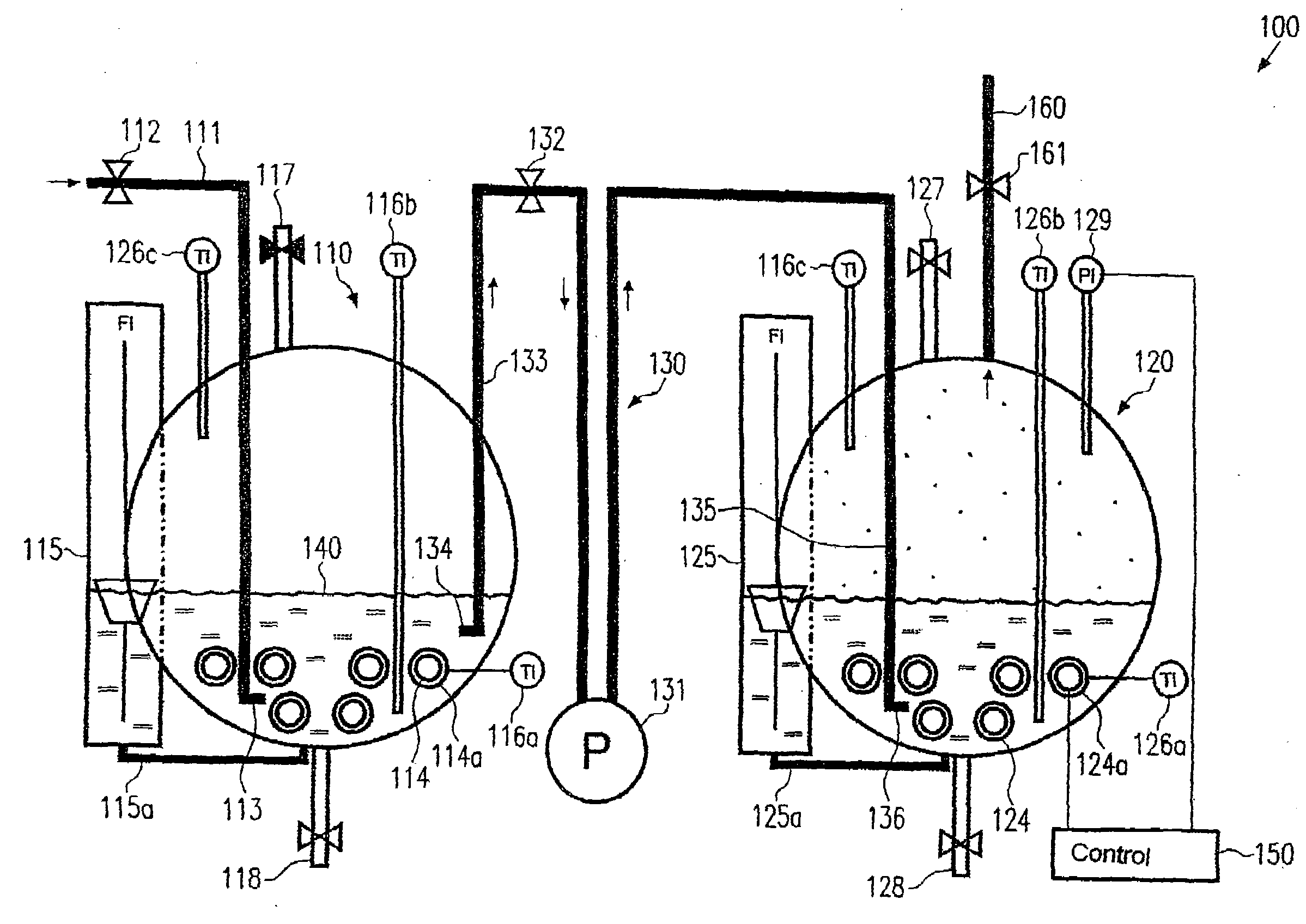
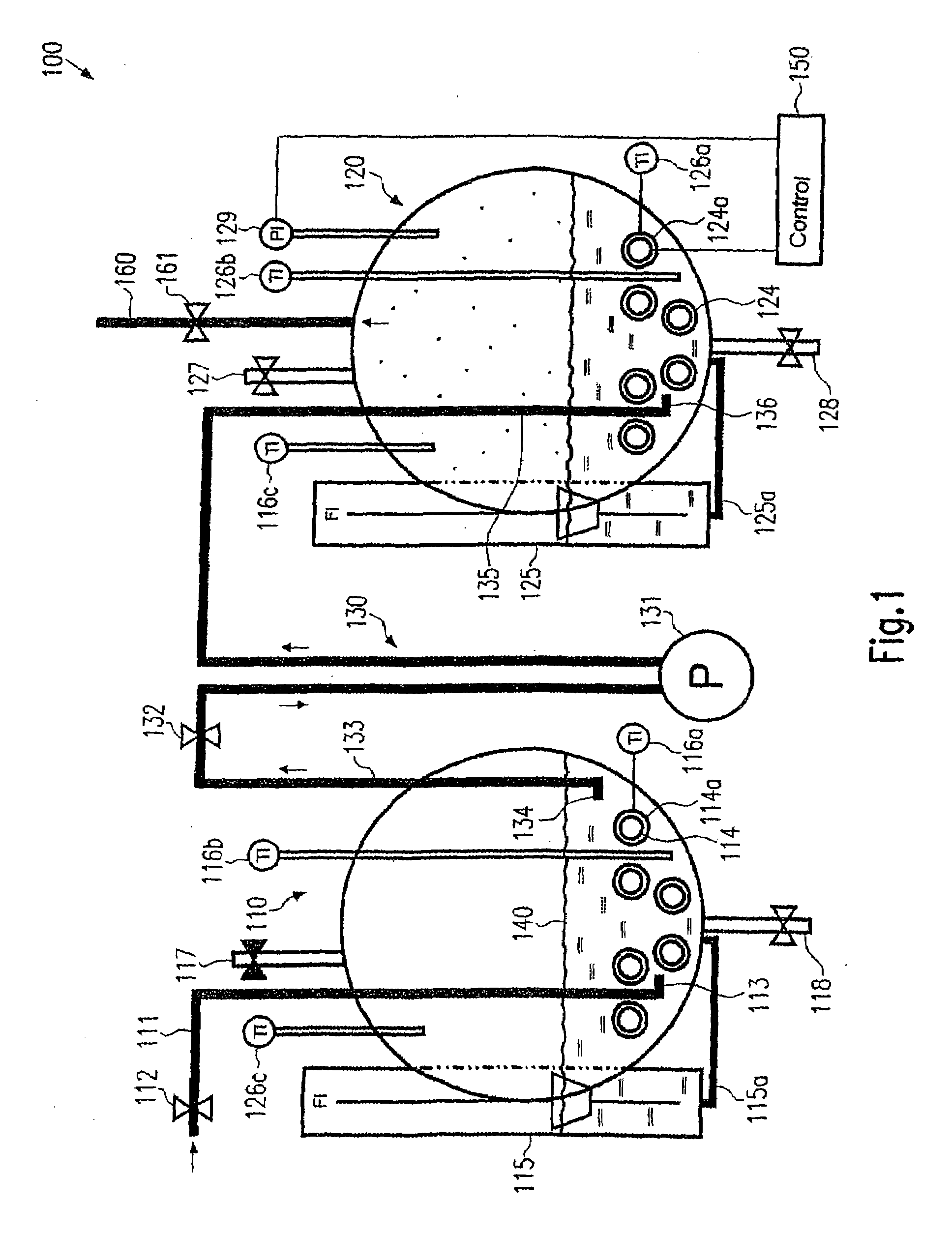
[0056]FIG. 1 is a schematic view showing a vapor generation system 100, wherein a preheating region 110 and a vapor generation region 120 are coupled by means of a fluid connection 130. The preheating region 110 comprises a supply line 111 which comprises a valve 112 at the inlet side and a flow outlet 113 at the outlet side. Preferably, the flow outlet 113 is arranged substantially horizontally in the operative position of the vapor generation system 100 to efficiently effect a convection flow in a liquid contained in the preheating region 110 during operation. The flow outlet 113 is preferably arranged deep below a liquid level 140. For instance, a typical distance of the flow outlet 113 from the liquid level 140 is within the range of several centimeters in a typical operative phase. To guarantee a correspondingly deep position of the flow outlet 113 for many possible liquid levels during operation, the flow outlet 113 may be arranged in the vicinity of the bottom area of the pre...


PUM

PropertyMeasurementUnit
boiling pointaaaaaaaaaa

Abstract

A method is provided for a soldering process. The method can include receiving a liquid phase heat transfer medium at a preheating container. The heat transfer medium can be received from an external supply. The method can also include heating the heat transfer medium to or above a predefined temperature that maintains the liquid phase and directing the heated heat transfer medium from the preheating container to an evaporation container. In the evaporation container, the heat transfer medium can be vaporized to convert the heat transfer medium from the liquid phase to a gas phase. Further, the method can include directing the gas phase heat transfer medium from the evaporation container to a solder chamber. The soldering process occurs in the solder chamber.

Description

CROSS REFERENCE TO RELATED APPLICATION[0001]This application is a divisional application of U.S. patent application Ser. No. 11 / 109,880, filed Apr. 20, 2005, entitled “Vapor-Generated Soldering System and Vapor Generation System for a Soldering System,” which is incorporated herein by reference in its entirety.BACKGROUND[0002]1. Field[0003]The present invention generally refers to soldering systems which are operated by means of a heat transfer medium which is present as vapor at least in part during the process. The present invention further refers to a vapor generation system which can be used for such soldering systems, e.g. condensation reflow-soldering systems, repair soldering systems, wave soldering systems, and selective soldering systems.[0004]2. Related Art[0005]When subassemblies are soldered by machine, use is made of soldering systems, for instance reflow soldering systems, in which heat is transferred to the individual components of the subassembly by means of radiatio...

Claims


Application Information

Patent Timeline
Patent Type & Authority Applications(United States)
IPC IPC(8): B23K31/12B23K31/02B23K1/015B23K3/08F22D3/04
CPCB23K3/08B23K1/015
Inventor BELL, HANSKOLB, WILFRIED
Owner REHM THERMAL SYST
Why Eureka
Try Eureka