Wavelength separator, planar illumination device and liquid crystal display device using the wavelength separator
a technology of wavelength separator and planar illumination, which is applied in the direction of planar/plate-like light guides, lighting and heating apparatus, instruments, etc., can solve the problems of insufficient effect, no specific construction for reducing power consumption, and increased power consumption, etc., to achieve high light utilization efficiency and low power consumption
- Summary
- Abstract
- Description
- Claims
- Application Information
AI Technical Summary
Benefits of technology
Problems solved by technology
Method used
Image

Examples
first embodiment
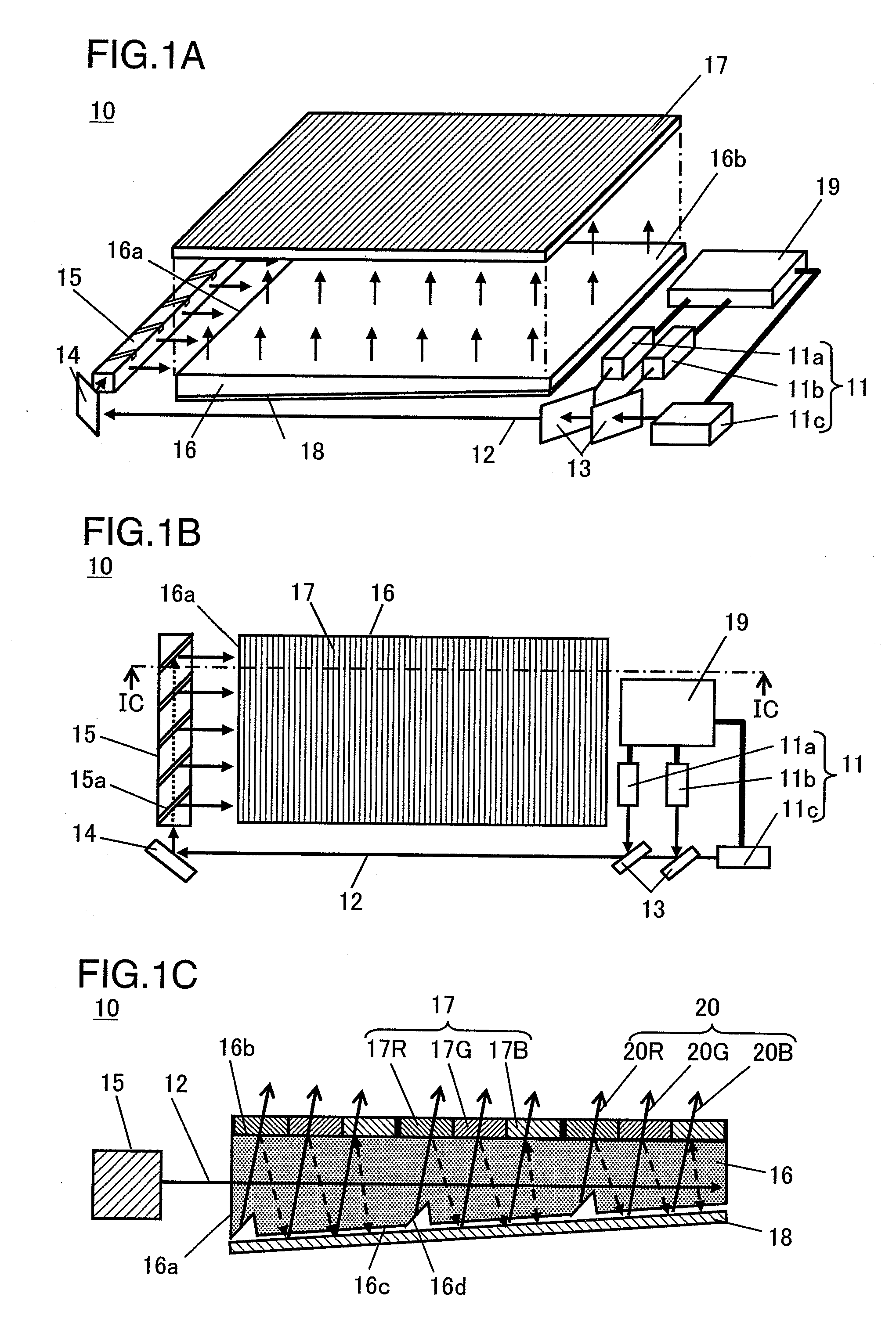
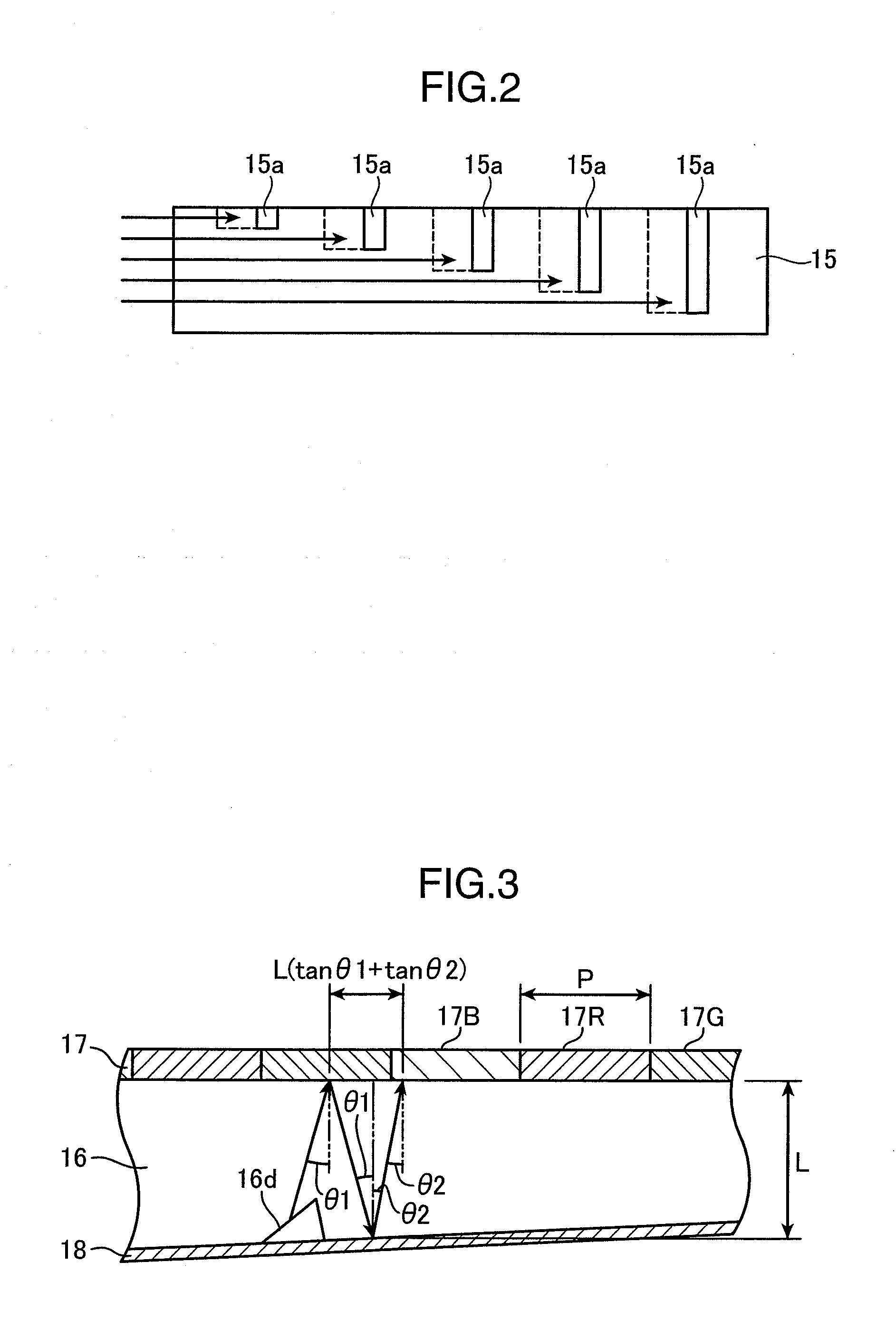
[0050]FIG. 1 are views showing a schematic construction of a planar illumination device according to a first embodiment of the present invention, wherein FIG. 1A is a perspective view diagrammatically showing the entire construction of the planar illumination device, FIG. 1B is a plan view of the planar illumination device and FIG. 1C is a section along IC-IC of FIG. 1B.
[0051]Although parts of the planar illumination device are shown to be separated in order to facilitate the understanding of the respective constructions in FIGS. 1A and 1B, they are placed on or within an unillustrated base plate or a frame in an actual construction to be entirely and integrally fixed.
[0052]Although a reflective color filter 17 is shown to be separated from a light guide plate 16 in order to facilitate the understanding of the construction, it is actually formed on a principal surface 16b of the light guide plate 16 as shown in FIG. 1C.
[0053]As shown in FIGS. 1A and 1B, a planar illumination device ...
second embodiment
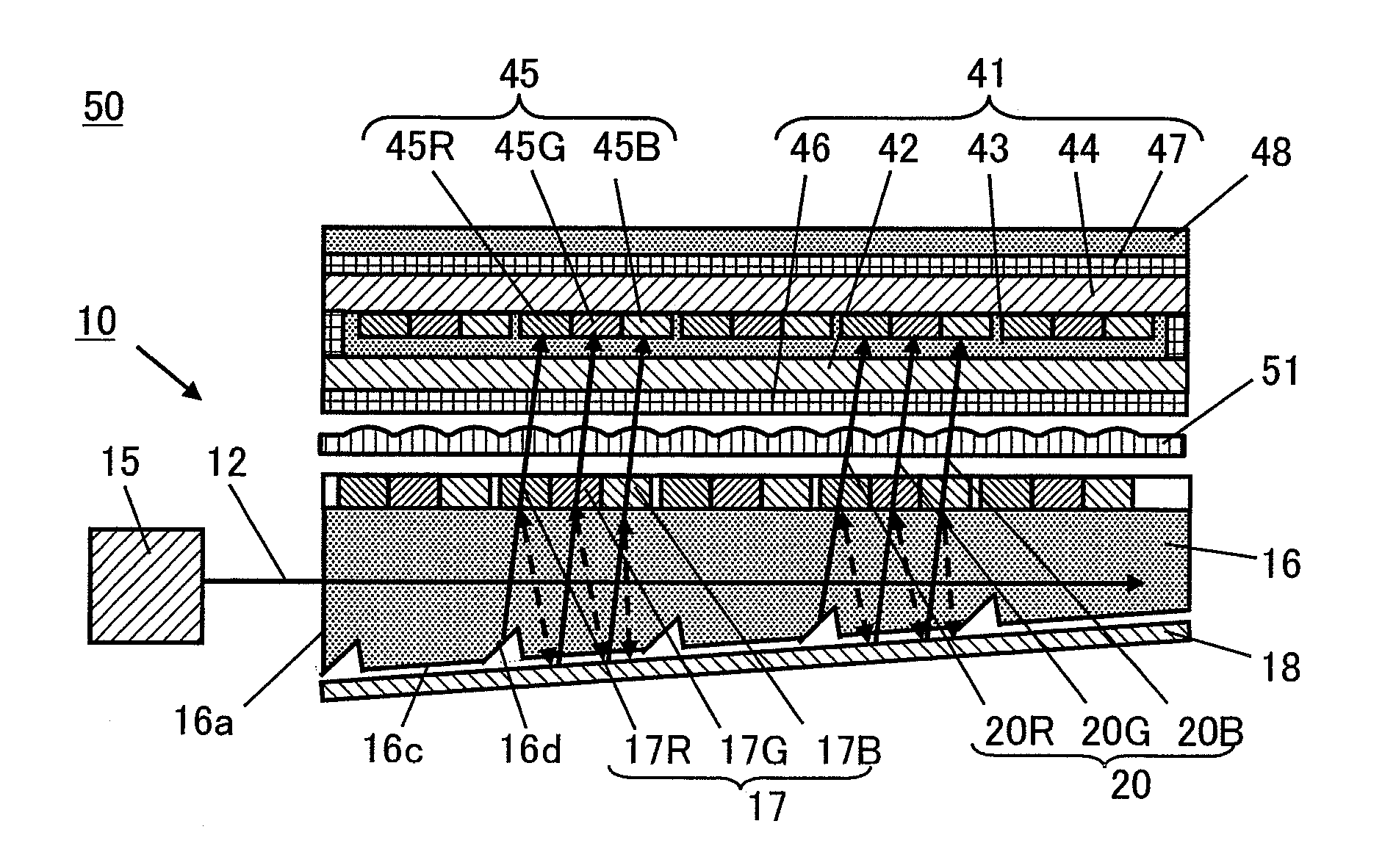
[0118]FIG. 7 are schematic views showing a liquid crystal display device according to a second embodiment of the invention, wherein FIG. 7A is a perspective view diagrammatically showing the entire construction of the liquid crystal display device and FIG. 7B is a plan view of the liquid crystal display device.
[0119]Although parts of the planar illumination device are shown to be separated in order to facilitate the understanding of the respective constructions in FIGS. 7A and 7B, they are placed on or within an unillustrated base plate or a frame in an actual construction to be entirely and integrally fixed.
[0120]As shown in FIGS. 7A and 7B, the liquid crystal display device 40 according to the second embodiment is provided with a liquid crystal panel 41, a backlight illumination device for illuminating the liquid crystal panel 41 from behind, e.g. the planar illumination device 10 described in the first embodiment, and a diffusion sheet 48 (seeFIG. 8).
[0121]FIG. 8 is a schematic s...
third embodiment
[0166]FIG. 12 are views showing a schematic construction of a liquid crystal display device 90 according to a third embodiment of the present invention, wherein FIG. 12A is a section of the liquid crystal display device and FIG. 12B is a perspective view of a structure sheet and diffusion sheet of FIG. 12A.
[0167]Although the structure sheet and the diffusion sheet are separated in order to facilitate the understanding in FIG. 12B, they are arranged in contact in an actual construction.
[0168]A liquid crystal display device 90 of the third embodiment shown in FIG. 12 differs from the liquid crystal display device 40 shown in FIG. 8 in that a structure sheet 91 is inserted between the emergent side polarizing plate 47 and a diffusion sheet 92 and black stripes 92a are provided. In FIG. 12, the same construction as the liquid crystal display device 40 of FIG. 8 are identified by the same reference numerals and not described.
[0169]As shown in FIGS. 12A and 12B, the structure sheet 91 inc...
PUM
 Abstract
Description
Claims
Application Information
 - R&D Engineer
- R&D Manager
- IP Professional
- Industry Leading Data Capabilities
- Powerful AI technology
- Patent DNA Extraction
Browse by: Latest US Patents, China's latest patents, Technical Efficacy Thesaurus, Application Domain, Technology Topic.
© 2024 PatSnap. All rights reserved.Legal|Privacy policy|Modern Slavery Act Transparency Statement|Sitemap