Power line communication apparatus, integrated circuit for power line communication and transmission/reception methods

a technology of power line communication and integrated circuit, which is applied in the direction of digital transmission, transmission, power distribution line transmission, etc., can solve the problems of communication errors, no specific standard has been established for the above-described plc technology, etc., and achieve the effect of easy notification

Inactive Publication Date: 2009-07-30
PANASONIC CORP
View PDF6 Cites 11 Cited by
  • Summary
  • Abstract
  • Description
  • Claims
  • Application Information

AI Technical Summary

Benefits of technology

[0012]According to this configuration, it is possible to easily notify a power line communication apparatus connected to the power line of the existence of the communication method of the another power line communication apparatus. Accordingly, it becomes possible to detect a state where a transmission signal is output to the common power line from a power line communication apparatus using a different type of communication method.

Problems solved by technology

However, no specific standard has been established for the above-described PLC technology.
This causes interference between signals transmitted from the plurality of communication apparatuses, thereby causing communication errors.

Method used


Image

  • Power line communication apparatus, integrated circuit for power line communication and transmission/reception methods
  • Power line communication apparatus, integrated circuit for power line communication and transmission/reception methods
  • Power line communication apparatus, integrated circuit for power line communication and transmission/reception methods

Examples


first embodiment

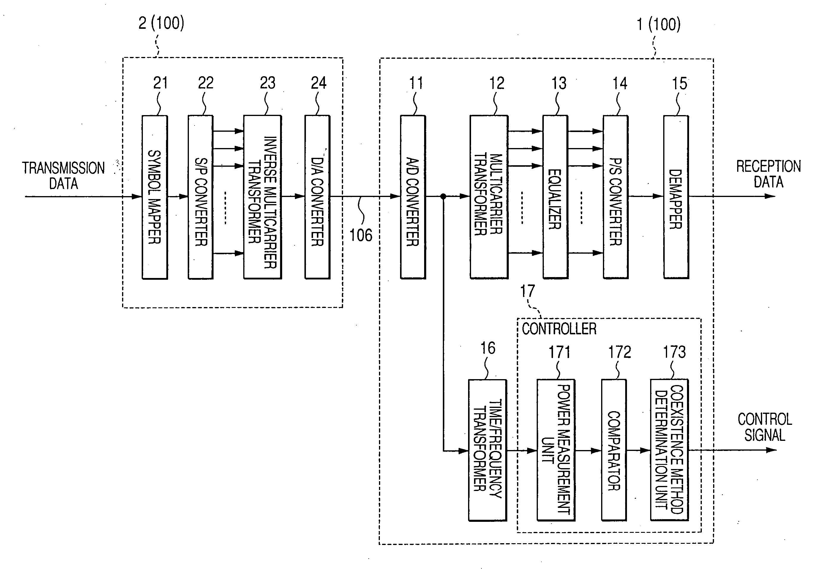
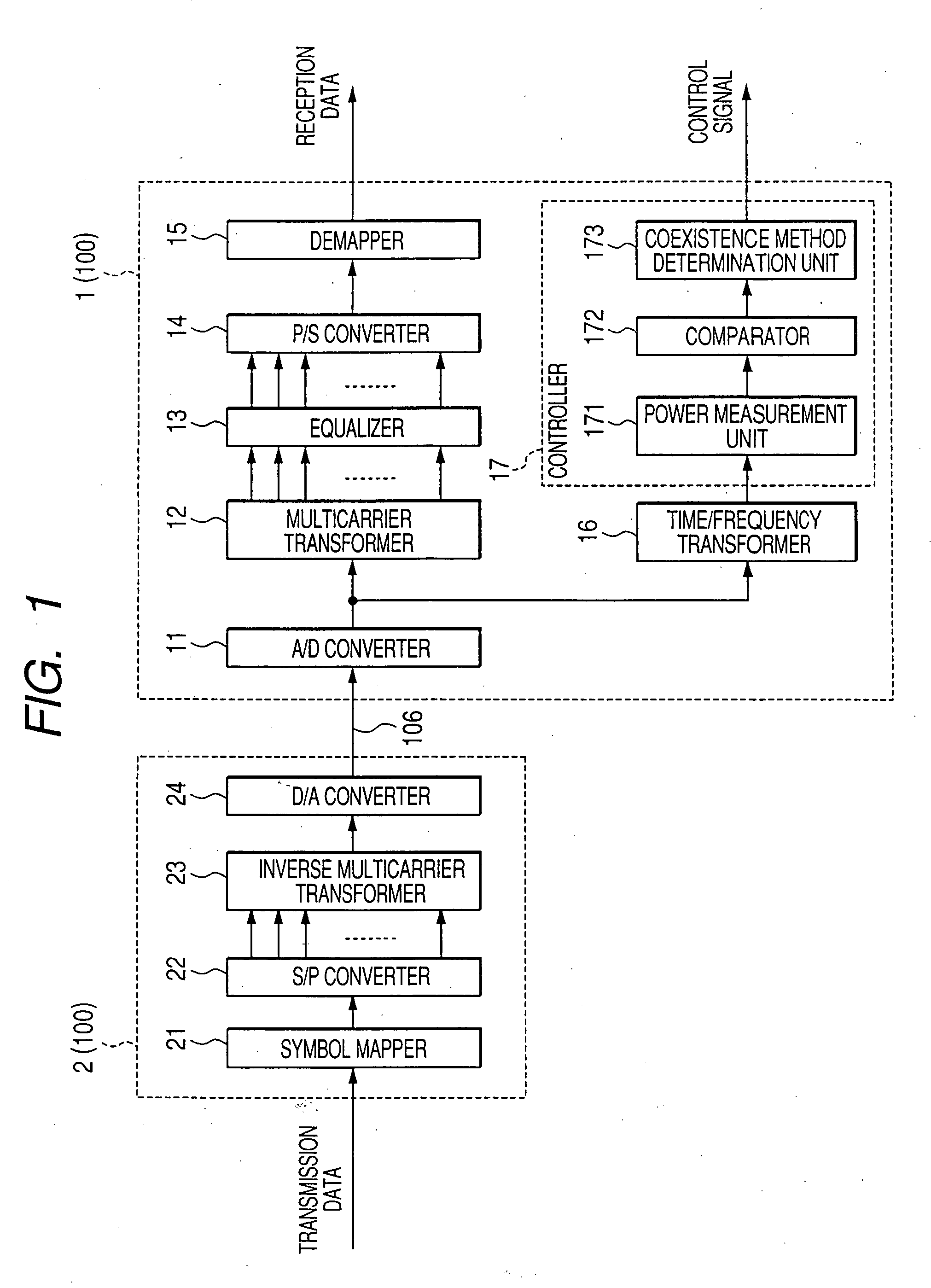
[0052]FIG. 1 is a block diagram illustrating a schematic configuration example of a transmitter and a receiver according to a first embodiment. Receiver 1 includes A / D converter 11, multicarrier transformer 12, equalizer 13, P / S converter 14, demapper 15, time / frequency transformer 16 such as FFT / DWT and controller17. Multicarrier transformer 12, such as a Fourier transformer (FFT) or a wavelet transformer (DWT), performs a desired time / frequency transformation. Equalizer 13 corrects a reception signal to reduce the effect of a transmission line. P / S converter 14 converts parallel data into serial data. Demapper 15 converts mapped symbol data into bit-data as a reception signal. Controller 17 performs a frequency analysis on a signal input from the power line as the transmission line. Controller 17 includes power measurement unit 171, comparator 172, and a coexistence method determination unit 173. Power measurement unit 171 measures power values as an example of frequency character...

second embodiment

[0077]The following describes a transmitter and a receiver according to a second embodiment. The configurations of the transmitter and the receiver according to the present embodiment are identical to those of the transmitter and the receiver according to the first embodiment.

[0078]FIG. 7 is a conceptual diagram illustrating an example of allocations of communication method identifying notches according to the second embodiment. The transmitter according to the present embodiment provides communication method identifying notches at a plurality of different frequency locations corresponding to respective communication methods. For instance, as shown in FIG. 7, communication method identifying notches NA1-NA3 are allocated to three different frequency locations for communication method A, while communication method identifying notches NB1-NB3 are allocated to three different frequency locations for communication method B.

[0079]FIG. 8 shows an example of attenuation frequency character...

third embodiment

[0087]The following describes a transmitter and a receiver according to a third embodiment. Configurations of the transmitter and the receiver according to the present embodiment are identical to those of the transmitter and the receiver according to the first embodiment.

[0088]FIG. 9 illustrates transmission and reception methods according to the third embodiment. As shown in FIG. 9, the transmission method according to the present embodiment sequentially generates a communication method identifying notch at least at one of frequency locations allocated in accordance with time passage.

[0089]As with FIG. 7, a description is provided for a case where communication method identifying notches NA1-NA3 are allocated to three different frequency locations for communication method A, while communication method identifying notches NB1-NB3 are allocated to three different frequency locations for communication method B. Transmitter 2 performs communications by communication method A.

[0090]Tran...


PUM


Abstract

Transmitter 2 includes inverse multicarrier transformer 23 and D / A converter 24. Inverse multicarrier transformer 23 generates a notch by masking a carrier at a frequency location predetermined in accordance with a communication method of the transmitter. D / A converter 24 performs a D / A conversion on a transmission signal containing the notch and transmits the signal to a transmission line. Receiver 1 includes power measurement unit 171, comparator 172 and coexistence signal determination unit 173. Power measurement unit 171 measures a power value of a signal input from the transmission line. Comparator 172 determines whether or not the notch exits by comparing the measured power value with a threshold. Coexistence method determination unit 173 determines the type of coexistence method, based on the location of the detected notch.

Description

TECHNICAL FIELD[0001]The present invention relates to a power line communication apparatus, an integrated circuit for power line communication, a transmission method and a reception method.BACKGROUND ART[0002]When using a terminal such as a computer for wire data communications at homes, offices, factories and the like, it is usually necessary to install wires such as cables and connectors to be used as transmission lines at such locations where they are needed. This requires a wide range of installation work before the communication system goes into operation.[0003]However, at homes, offices and factories, commercial power supply of, for example, 100V AC-50 / 60 Hz in Japan and 120V AC-60 Hz in the United States of America is generally used. Therefore, power lines (electric lamp lines) for supplying such power are already installed everywhere in homes, offices and factories. Utilizing these power lines for data communications thus eliminates the need to newly install exclusive wires ...

Claims


Application Information

Patent Timeline
Patent Type & Authority Applications(United States)
IPC IPC(8): H04B3/00
CPCH04B3/542H04B2203/5425H04L27/2601H04B2203/5491H04B2203/5495H04B2203/5483H04B3/54H04B2203/5408H04L27/0012
Inventor KOGA, HISAOKODAMA, NOBUTAKAIGATA, YUJIKUROBE, AKIOIKEDA, KOJIKURODA, GO
Owner PANASONIC CORP
Why Eureka
Try Eureka