Communication systems

a communication system and wireless communication technology, applied in the field of interference mitigation in wireless communication systems, can solve the problems of affecting the level of interference, and the interference of radio transmissions occupying the same parts of the shared communication spectrum. to achieve the effect of reducing the interference level

a communication system and wireless communication technology, applied in the field of interference mitigation in wireless communication systems, can solve the problems of affecting the level of interference, and the interference of radio transmissions occupying the same parts of the shared communication spectrum. to achieve the effect of reducing the interference level

US20090191906A1Active Publication Date: 2009-07-30FUJITSU LTD

Image

  • Communication systems
  • Communication systems
  • Communication systems

Examples


Embodiment Construction

[0068]A system for spectrum sharing and coexistence of system apparatuses, including the possibility of spectrum exchange between two or more RANs has been considered, for the purposes of attaining better utilisation of spectrum for wireless mobile networks. An example of such a system is the WINNER project already mentioned, which is currently under development.

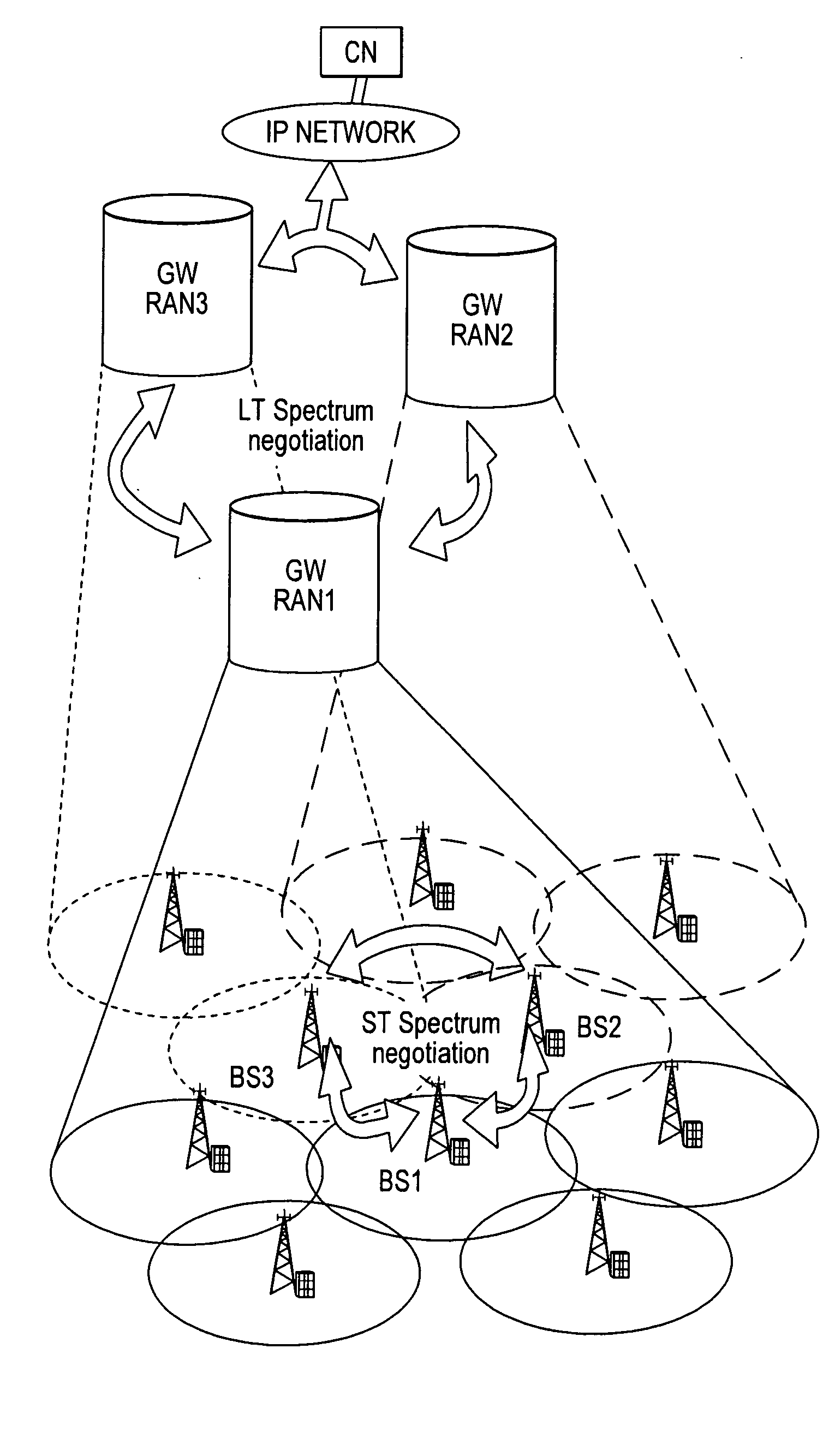
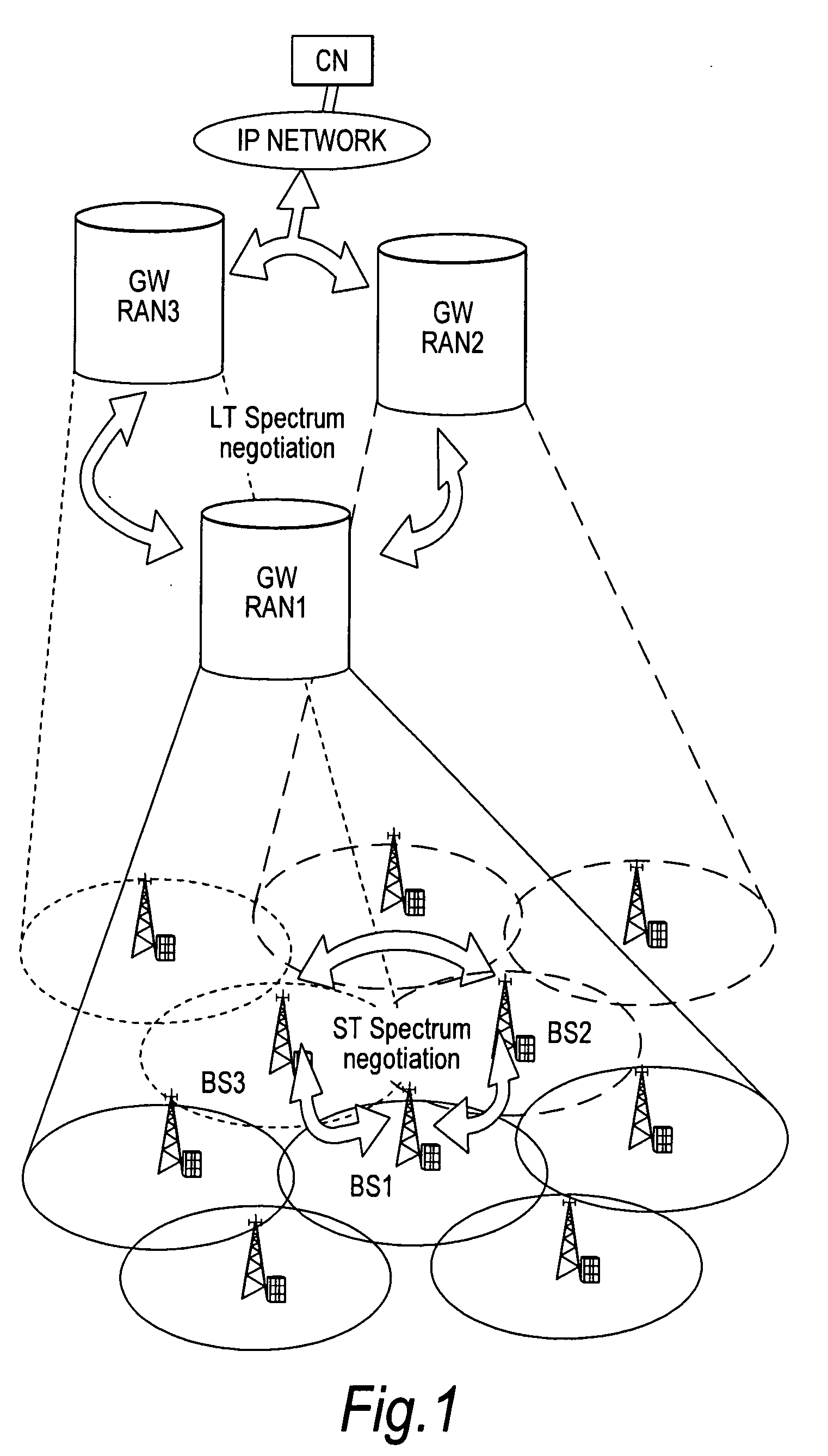
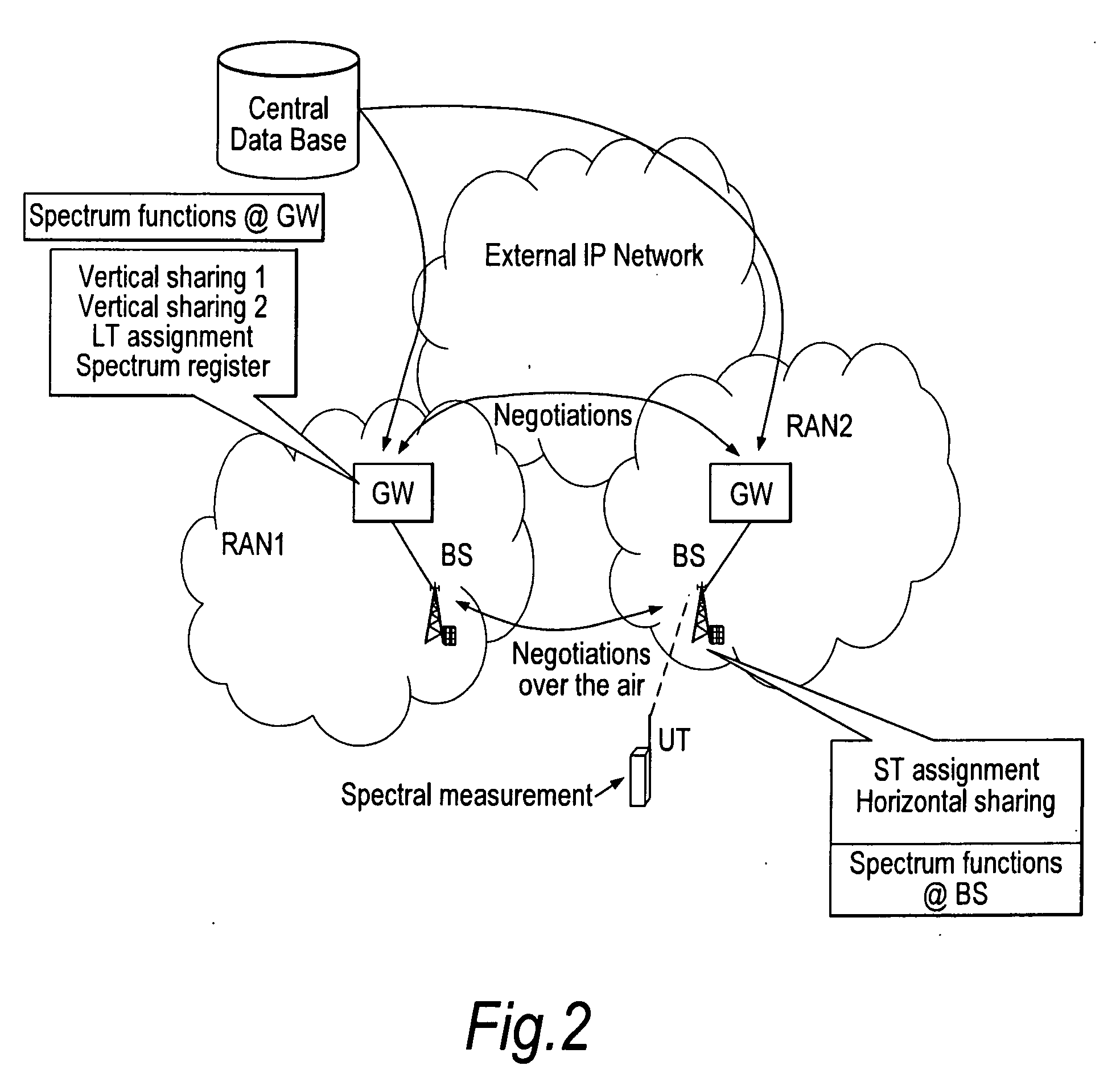
[0069]FIG. 2 is a schematic diagram of simplistic network architecture useful for understanding the concept of spectrum sharing. The network ofFIG. 2 may to some extent be compared to the schematic diagram of FIG. 1. The basic idea is to enable independent RANs (Radio Access Networks) to use each other's spectrum when it is not needed. Negotiations between different RANs may be carried out by communications between the gateways of those RANs. The independent RANs may use the same technological standards (radio access technology), as envisaged in WINNER for example. On the other hand, the RANs may use different standards whil...


PUM


Abstract

A wireless communication system is comprised of multiple radio access networks—RANs—which at least partly share the same frequency spectrum. Each RAN is provided with a gateway—GW—(GW1, GW2, GW3) for managing the network. Spectrum sharing in the system is achieved through a hierarchy of processes including long-term—LT—spectrum assignment, short-term—ST—spectrum assignment, and dynamic channel allocation, the latter process assigning sub-channels to base stations (BS1, . . . BS5; BS6, . . . BS10; BS11, . . . BS16) in each RAN. However, so-called “red” sub-channels (subject to interference) are liable to arise.

Description

FIELD OF THE INVENTION [0001]The present invention relates to interference mitigation in wireless communication systems, more particularly to systems in which multiple networks (radio access networks or RANs) co-exist.BACKGROUND OF THE INVENTION [0002]In a radio access network, communication apparatuses of the network generally communicate (with one another, and / or with other communication apparatuses) using radio transmissions that share the same transmission medium (commonly, the surrounding atmosphere). Although such radio transmissions are normally configured to occupy allocated or assigned frequency bands (also called sub-channels, and which may be divided in time to form “chunks”), the radio-frequency spectrum is nevertheless shared by such transmissions.[0003]Radio transmissions occupying the same parts of the shared communication spectrum can interfere with one another. The level of interference will depend on a number of factors, for example on the power levels of the respe...

Claims


Application Information

Patent Timeline
30 Jul 2009
Publication
US20090191906A1
IPC
H04B15/00
CPC
H04W16/14; H04W24/00; H04W72/082; H04W28/16; H04W28/04; H04W72/541
Inventors
ABEDI, SAIED