Power-saving network apparatus and method thereof

a network apparatus and power-saving technology, applied in the direction of instruments, power supply for data processing, liquid/fluent solid measurement, etc., can solve the problems of insufficient power-saving effect of such mechanisms, increased and slightly lower power consumption of network systems. , to achieve the effect of low power sta

Active Publication Date: 2009-07-30
REALTEK SEMICON CORP
View PDF4 Cites 40 Cited by
  • Summary
  • Abstract
  • Description
  • Claims
  • Application Information

AI Technical Summary

Problems solved by technology

In a high-speed network system, such as 1 Gbase-T / 10 Gbase-T Ethernet system, the power consumption of the network system increases correspondingly if its circuits operate frequently.
However, when the network system is in the link state, the power-saving effect of such mechanism is not good enough, due to all of the circuits of the transmitter and the receiver being still in power-on state.
At this time, the power consumption of the network system is slightly lower than the power consumption in the normal state (i.e., transmitting the packets), which is actually not cost-effective.

Method used


Image

  • Power-saving network apparatus and method thereof
  • Power-saving network apparatus and method thereof
  • Power-saving network apparatus and method thereof

Examples


first embodiment

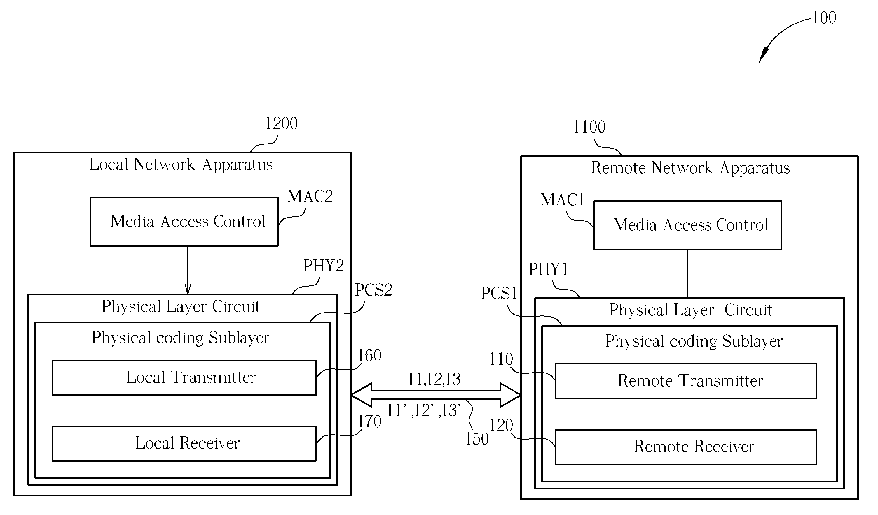
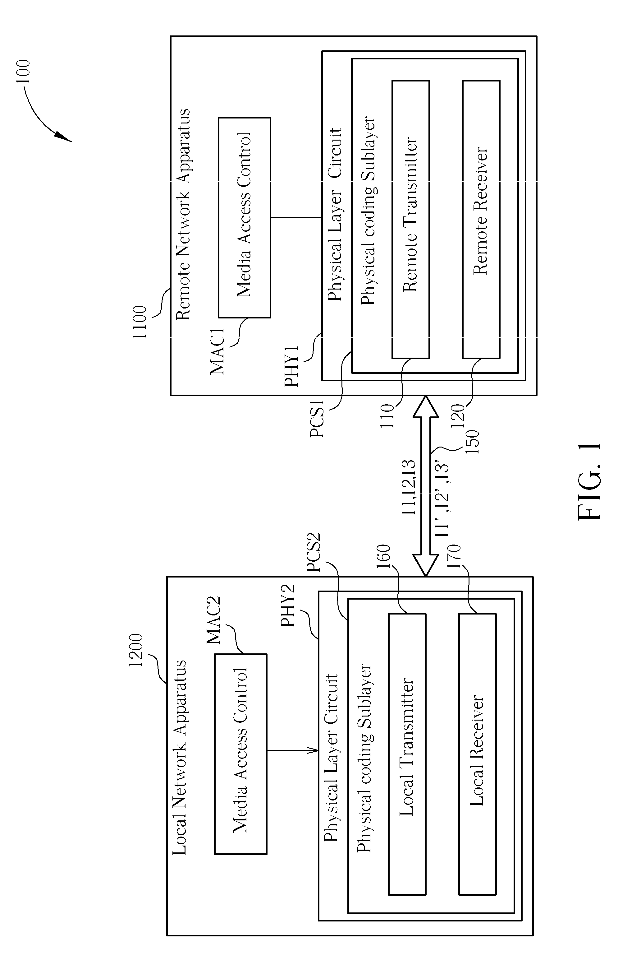
[0018]Please refer to FIG. 1. FIG. 1 is a diagram of a network system 100 with power-saving mechanism according to the present invention. As shown in FIG. 1, the network system 100 includes, but is not limited to, a remote network apparatus 1100 and a local network apparatus 1200, wherein the local network apparatus 1200 maintains a connection with the remote network apparatus 1100 through a physical line 150. The remote network apparatus 1100 includes a media access controller MAC1 and a physical layer circuit PHY1. The media access controller MAC1 generates output packets and processing input packets of the remote network apparatus 1100. The physical layer circuit PHY1 includes a physical coding sublayer PCS1 for decoding and encoding the transmitted / received data. The physical coding sublayer PCS1 of the remote network apparatus 1100 has a remote transmitter 110 and a remote receiver 120. On the other hand, the local network apparatus 1200 also includes a media access controller ...

second embodiment

[0043]Please refer to FIG. 4. FIG. 4 is a diagram of a network system 400 with power-saving mechanism according to the present invention. The architecture of the network system 400 in FIG. 4 is similar to the network system 100 in FIG. 1, and the difference between them is that the remote network apparatus 4100 of the network system 400 further disposes a buffer 420 and a first judging module 440, wherein the buffer 420 is disposed in the remote transmitter 410. In addition, the local network apparatus 4200 of the network system 400 further disposes a buffer 470 and a second judging module 490, wherein the buffer 470 is disposed in the local transmitter 460. If the local network apparatus 4200 is acted as the local network device, the local network apparatus 4200 utilizes the buffer 470 of the local transmitter 460 to store the output packets during a duration of the local transmitter 460 entering the normal state SI from the low power state S2. The second judging module 490 determi...


PUM


Abstract

A power-saving network apparatus includes a MAC and a PHY. The PHY includes a transmitter and a receiver. The transmitter executes the operations of: transmitting a data signal to a remote network apparatus according to output packets of the MAC when the transmitter enters a normal state; transmitting an idle signal to the remote network apparatus when the transmitter enters an idle state; transmitting an indication signal to the remote network apparatus to notify it to enter a low power state, wherein the indication signal is different from the idle signal; entering the idle state or the normal state from the low power state in response to at least one of a predetermined period and a transmitting enable signal.

Description

CROSS REFERENCE TO RELATED APPLICATIONS[0001]This application claims the benefit of U.S. Provisional Application No. 61 / 021,904, which was filed on Jan. 18, 2008 and is incorporated herein by reference. In addition, this application claims priority of Taiwanese Application No. 098101499, filed on Jan. 16, 2009 and is incorporated herein by reference.BACKGROUND OF THE INVENTION[0002]1. Field of the Invention[0003]The present invention relates to a power-saving method applied to a network system and a related apparatus, and more particularly, to a method and a related apparatus capable of entering and leaving a low power state in the PHY layer to save power.[0004]2. Description of the Prior Art[0005]In a high-speed network system, such as 1 Gbase-T / 10 Gbase-T Ethernet system, the power consumption of the network system increases correspondingly if its circuits operate frequently. Hence, how to save the power consumption of the network system becomes an important topic of the field.[00...

Claims


Application Information

Patent Timeline
Patent Type & Authority Applications(United States)
IPC IPC(8): G06F15/16G06F1/32
CPCH04L69/323G06F1/3209
Inventor KUO, SHIEH-HSINGTSENG, TA-CHINLI, MING-JEYU, TING-FA
Owner REALTEK SEMICON CORP
Why Eureka
Try Eureka