Parking lock arrangement

a technology for parking locks and locking mechanisms, applied in the direction of limiting/preventing/returning movement of parts, controlling members, controlling members, etc., can solve the problems of affecting the tolerance of the speed with which the parking lock engages, occupying a relatively large space, and affecting the tolerance of the parking lock

Active Publication Date: 2009-08-06
GETRAG GETRIEBE & ZAHNRADFABRIK HERMANN HAGENMEYER GMBH & CO KG
View PDF2 Cites 34 Cited by
  • Summary
  • Abstract
  • Description
  • Claims
  • Application Information

AI Technical Summary

Benefits of technology

[0046]This measure serves to prevent the drive member accidentally detaching itself from the recess.
[0047]According to a further preferred embodiment a detent device is also fixed to the actuating mechanism. This allows the locki

Problems solved by technology

The known parking lock arrangement has a relatively large number of components and takes up a relatively large amount of space.
Such springs furthe

Method used


Image

  • Parking lock arrangement
  • Parking lock arrangement

Examples


Embodiment Construction

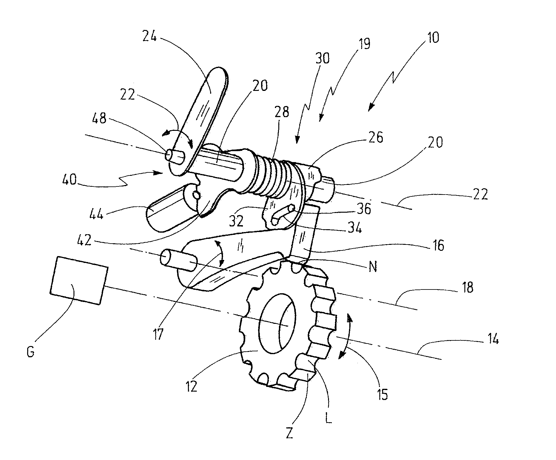
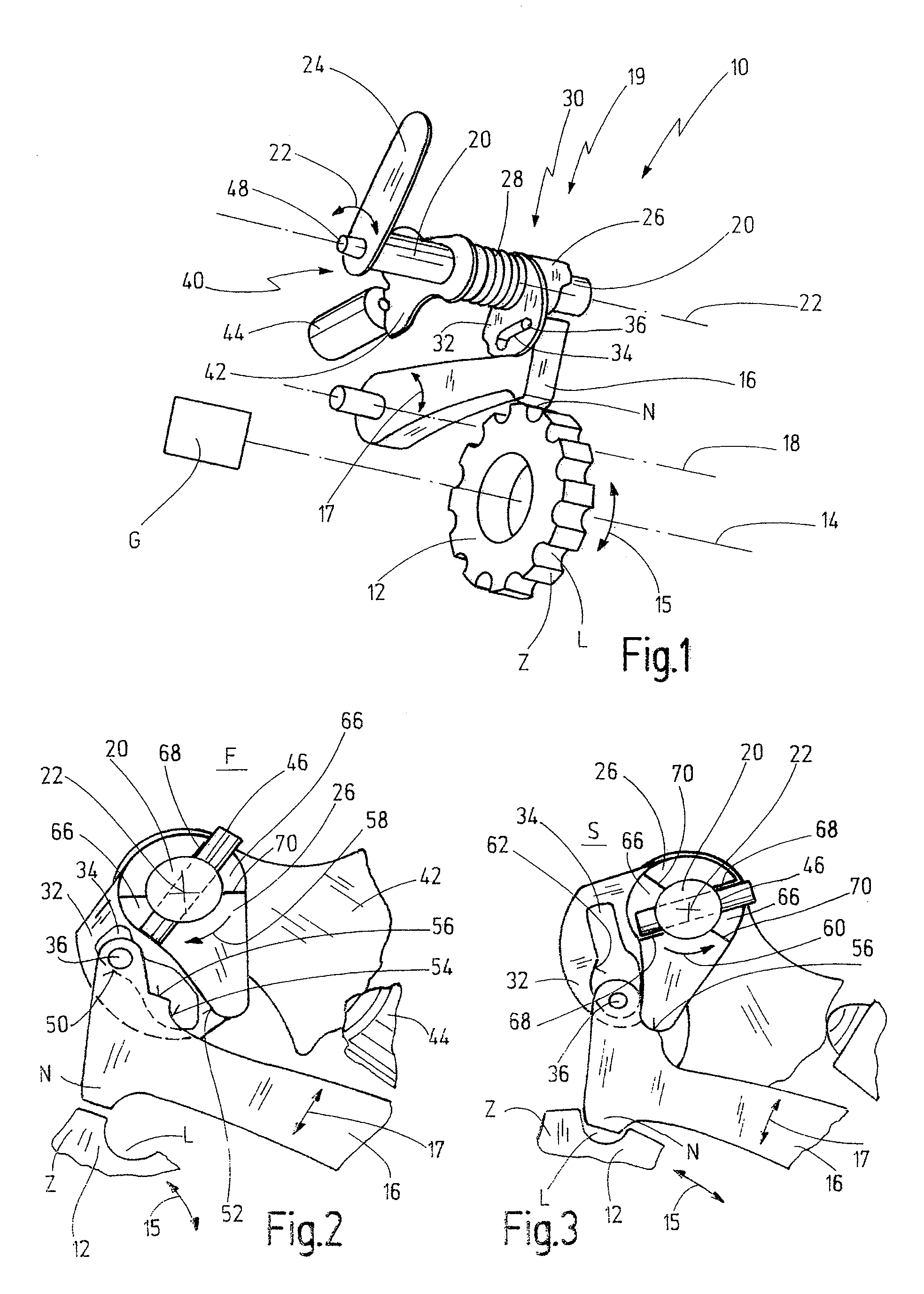
[0053]FIG. 1 in schematic form represents a gearbox G, to which a parking lock arrangement, generally denoted by 10, is assigned.

[0054]The parking lock arrangement 10 has a parking lock cog 12, which in the manner of a spur gear comprises teeth Z and tooth gaps L on its outer circumference. The parking lock cog 12 is rotatable about a first axis 14, as is represented by the numeral 15.

[0055]The parking lock arrangement 10 furthermore has parking lock pawl 16, which is capable of pivoting about a second axis 18, as is indicated by 17. The second axis 18 runs at a distance from the first axis 14 approximately parallel thereto.

[0056]The parking lock arrangement 10 further comprises an actuating mechanism 19, by means of which the parking lock pawl 16 can be pivoted from a release position into a locking position. In the locking position a projection N provided at the outer end of the parking lock pawl 16 engages in a tooth gap L in the parking lock cog 12. The parking lock pawl 16 is h...


PUM


Abstract

A parking lock arrangement for a motor vehicle gearbox. A parking lock cog can be fixed to a shaft of the motor vehicle gearbox rotatable about a first axis. A parking lock pawl is supported so that it can pivot about a second axis. An actuating mechanism can pivot the parking lock pawl into a locking position, in which the parking lock pawl meshes with the parking lock cog. A release mechanism can pivot the parking lock pawl out of the locking position into a release position, in which the parking lock pawl is decoupled from the parking lock cog. The actuating mechanism has a cam, which is supported so that it can pivot about a third axis and which in a first cam position holds the parking lock pawl in the locking position.

Description

CROSS REFERENCE TO RELATED APPLICATIONS[0001]This application claims the priority of German utility application DE 20 2008 001 760.1, filed Feb. 1, 2008.BACKGROUND OF THE INVENTION[0002]The present invention relates to a parking lock arrangement for a motor vehicle gearbox, with a parking lock cog, which can be fixed to a shaft of the motor vehicle gearbox rotatable about a first axis, a parking lock pawl, which is supported so that it can pivot about a second axis, an actuating mechanism, by means of which the parking lock pawl can be pivoted into a locking position, in which the parking lock pawl meshes with the parking lock cog, and a release mechanism, by means of which the parking lock pawl can be pivoted out of the locking position into a release position, in which the parking lock pawl is decoupled from the parking lock cog.[0003]Such parking lock arrangements are generally known, being disclosed by DE 103 10 977 A1, for example.[0004]As actuating mechanism, the parking lock ...

Claims


Application Information

Patent Timeline
IPC IPC(8): G05G5/18
CPCY10T74/214Y10T74/2137F16H63/3416Y10T74/19637F16H63/3433
Inventor BURGARDT, GEORGKAPP, STEFAN
Owner GETRAG GETRIEBE & ZAHNRADFABRIK HERMANN HAGENMEYER GMBH & CO KG
Why Eureka
Try Eureka