
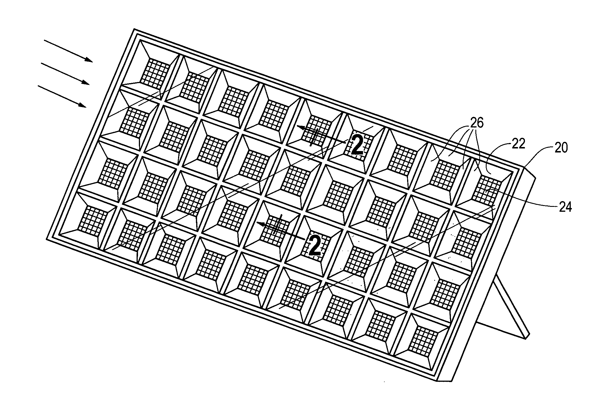
Method and apparatus for arranging multiple flat reflector facets around a solar cell or solar panel

a solar cell or solar panel technology, applied in the field of solar panels, can solve the problems of high cost of solar photovoltaic cells, high cost of materials used to convert solar energy into thermal or electrical energy, inefficient or wasteful use of expensive materials, etc., and achieve the effect of generating more power

Inactive Publication Date: 2009-08-06
SIMON DANIEL
View PDF27 Cites 13 Cited by
  • Summary
  • Abstract
  • Description
  • Claims
  • Application Information

AI Technical Summary

Problems solved by technology

Even as the cost of other energy sources rise, a main obstacle to widespread adoption of solar power is the high cost of solar devices, especially solar photovoltaic cells.
This is generally due to the high cost of materials used to convert solar energy into thermal or electrical energy, especially relative to reflector materials.
While these arrangements reduce the amount of costly solar cell materials somewhat, they still include the inefficient or wasteful use of expensive materials.
Disadvantages of these types of arrangements include complex geometries which are difficult to make and costly to reproduce.

Method used


Image

  • Method and apparatus for arranging multiple flat reflector facets around a solar cell or solar panel
  • Method and apparatus for arranging multiple flat reflector facets around a solar cell or solar panel
  • Method and apparatus for arranging multiple flat reflector facets around a solar cell or solar panel

Examples


Embodiment Construction

[0027]The present invention uses a simple arrangement of flat reflectors or reflective facets arranged around a solar cell or solar panel to increase the amount of light arriving at the solar cell or panel, with the object of reducing the average cost of solar power.

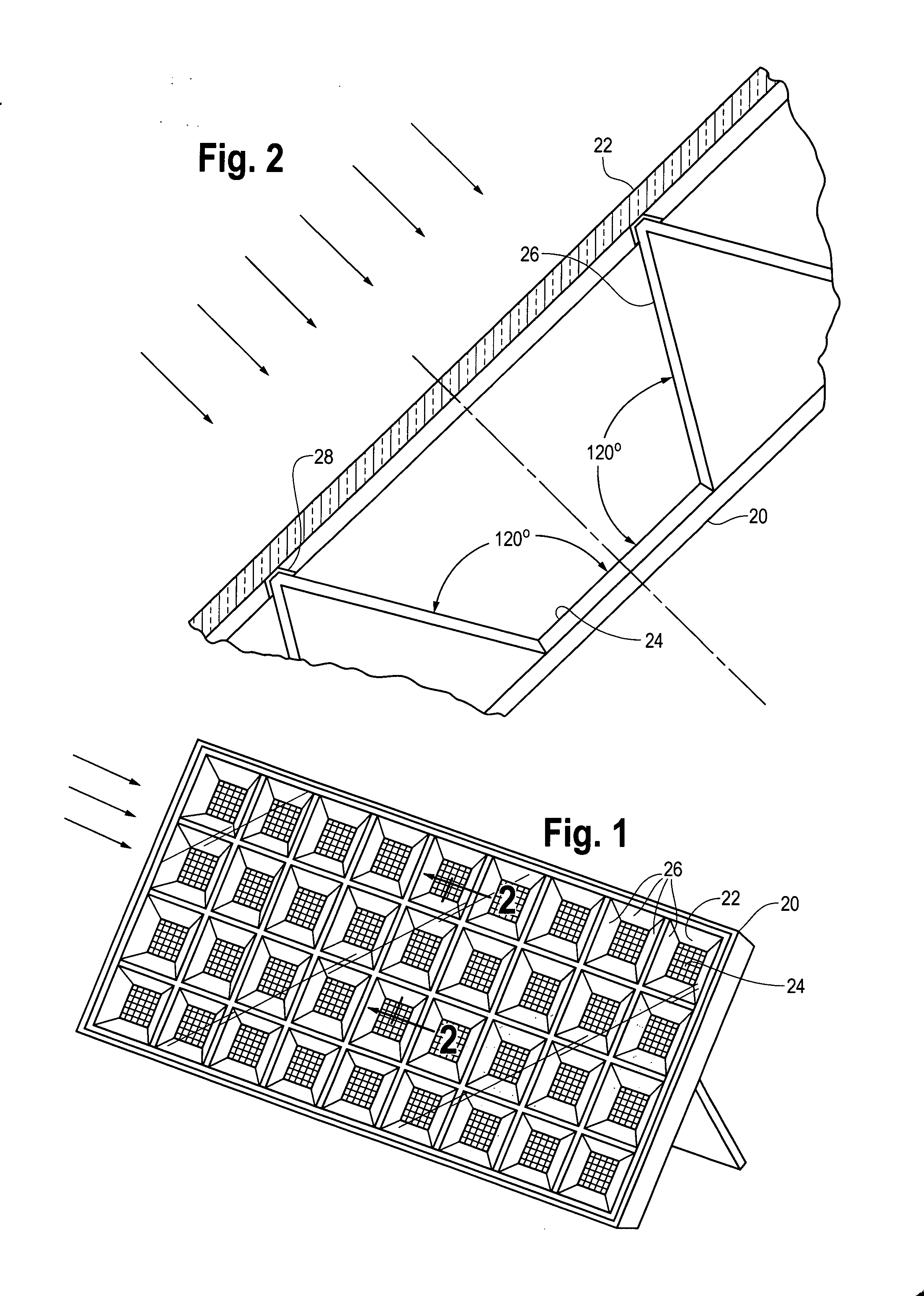
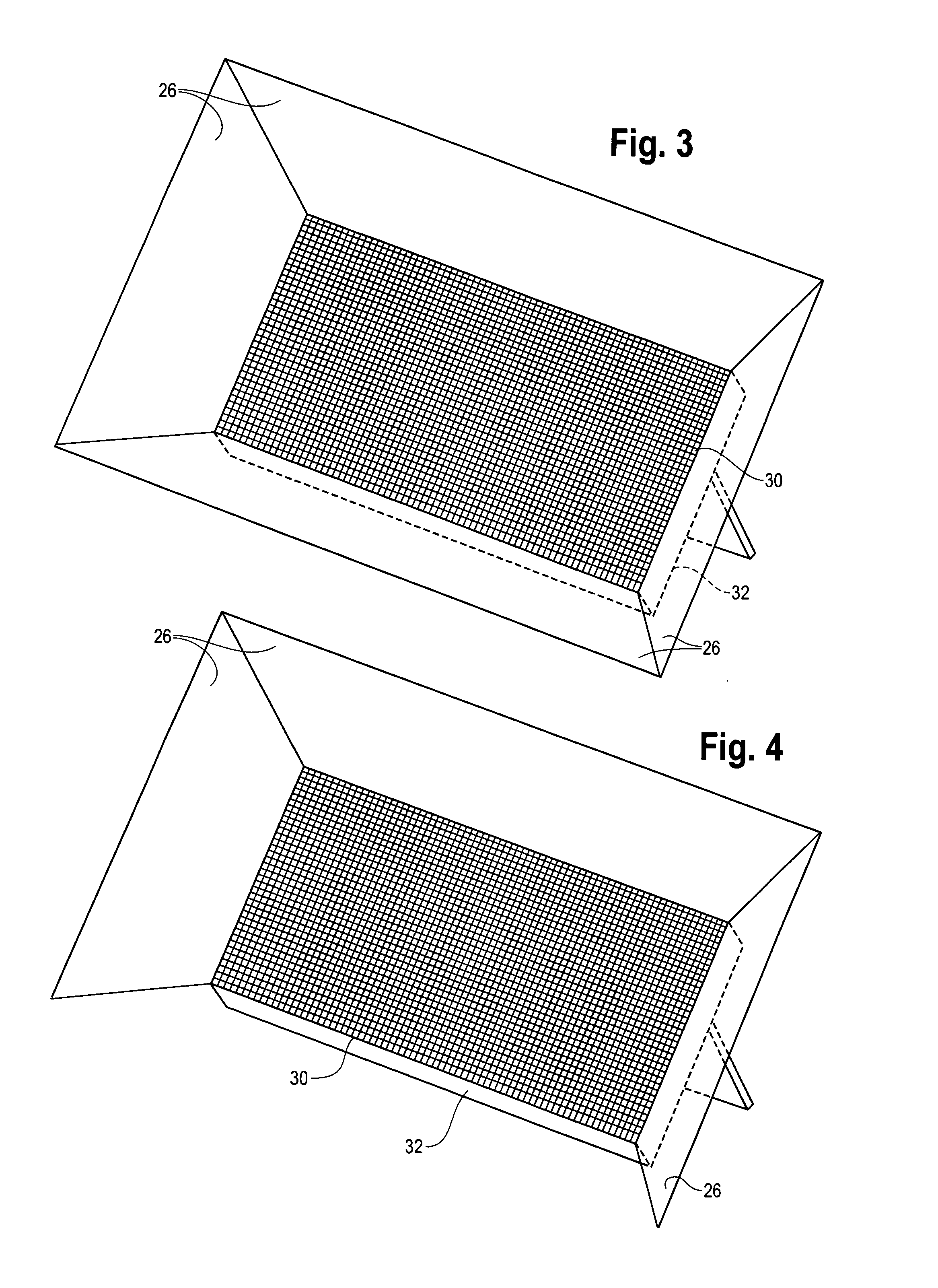
[0028]FIG. 1 shows a perspective view of a solar panel constructed according to an embodiment of this invention. Similar to prior art solar panels, this invention employs a repeating pattern of solar cells 24 that are contained within a panel frame 20 and disposed parallel to and under a transparent cover 22. Unlike prior art solar panels, in the preferred embodiment each solar cell 24 has a reflective facet 26 located adjacent to each side of the solar cell 24, which is disposed at an obtuse angle relative to the solar cell 24 and extending upward toward the transparent cover 22. Assuming the solar cell 24 is approximately square (quite common), each of the four reflective facets 26 will be flat and have an equivalent i...


PUM


Abstract

A system and method of arranging multiple flat reflective facets around solar cells within a solar panel, or around a standard solar panel to increase the amount of light striking the solar cells or panel. The present invention in the preferred embodiment uses multiple reflector facets arranged to form an inverted pyramid shell where the apex of the pyramid is removed and replaced by a solar cell or panel. Accordingly each flat reflective facet has an isosceles trapezoid shape and has its shorter parallel side located adjacent and at a 120 degree angle to the solar cell or panel. This geometry ensures uniform illumination of the solar cell provided the reflector is approximately the same width as the solar cell; such uniform illumination may be especially helpful for PV generating applications. An alternate embodiment employs only three flat reflective facets, rather than four, around a standard solar panel. Flat reflective facets cost less than solar cells or panels, so employing these arrangements should lower the average cost of solar power.

Description

BACKGROUND[0001]1. Field of Invention[0002]This invention relates generally to solar panels and more specifically to an improved arrangement of multiple reflector facets around solar cells within a solar panel, or alternately around the outside of solar panels.[0003]2. Description of the Prior Art[0004]There is a substantial interest in the commercial application of solar energy. Even as the cost of other energy sources rise, a main obstacle to widespread adoption of solar power is the high cost of solar devices, especially solar photovoltaic cells. This is generally due to the high cost of materials used to convert solar energy into thermal or electrical energy, especially relative to reflector materials. It is well known in the art to use a solar cell for intercepting sunlight and producing energy of a thermal or electrical nature or the combination of both. A solar device or solar cell generally can mean a receiver or thermal absorbing plate (for solar thermal applications) or a ...

Claims


Application Information

Patent Timeline
Patent Type & Authority Applications(United States)
IPC IPC(8): H01L31/058H01L31/0232F24J2/46
CPCF24J2/16F24J2002/108F24J2002/4659H01L31/0547Y02E10/52H02S20/00Y02E10/40F24S2023/872F24S2025/6001F24S23/77
Inventor SIMON, DANIEL
Owner SIMON DANIEL
Learn More