
Multi-stage height control valve including position sensitive pilot signal and pressure boost for vehicle air springs

a multi-stage, height control valve technology, applied in suspensions, shock absorbers, transportation items, etc., can solve the problems of relative rough ride, difficulty in determining by the vehicle operator, and exhausting air from the air springs

Active Publication Date: 2009-08-06
HENDRICKSON USA L L C
View PDF18 Cites 27 Cited by
  • Summary
  • Abstract
  • Description
  • Claims
  • Application Information

AI Technical Summary

Benefits of technology

The present invention provides a multi-stage height control valve for a pneumatic control system of a vehicle. The valve can signal when a secondary ride height has been achieved by the vehicle, and can control the inflation and exhaust of the air springs to achieve the primary design ride height. The valve can also potentially increase axle / suspension system performance and longevity, and reduce wear and premature failure of the components.

Problems solved by technology

Early suspension designs included heavy leaf-spring suspensions which resulted in a relatively rough ride to the cargo and / or passengers carried by the vehicle, and did not allow loads to equalize among the axles in all situations, thus creating the need for an axle / suspension system with softer ride characteristics and more efficient equalization characteristics.
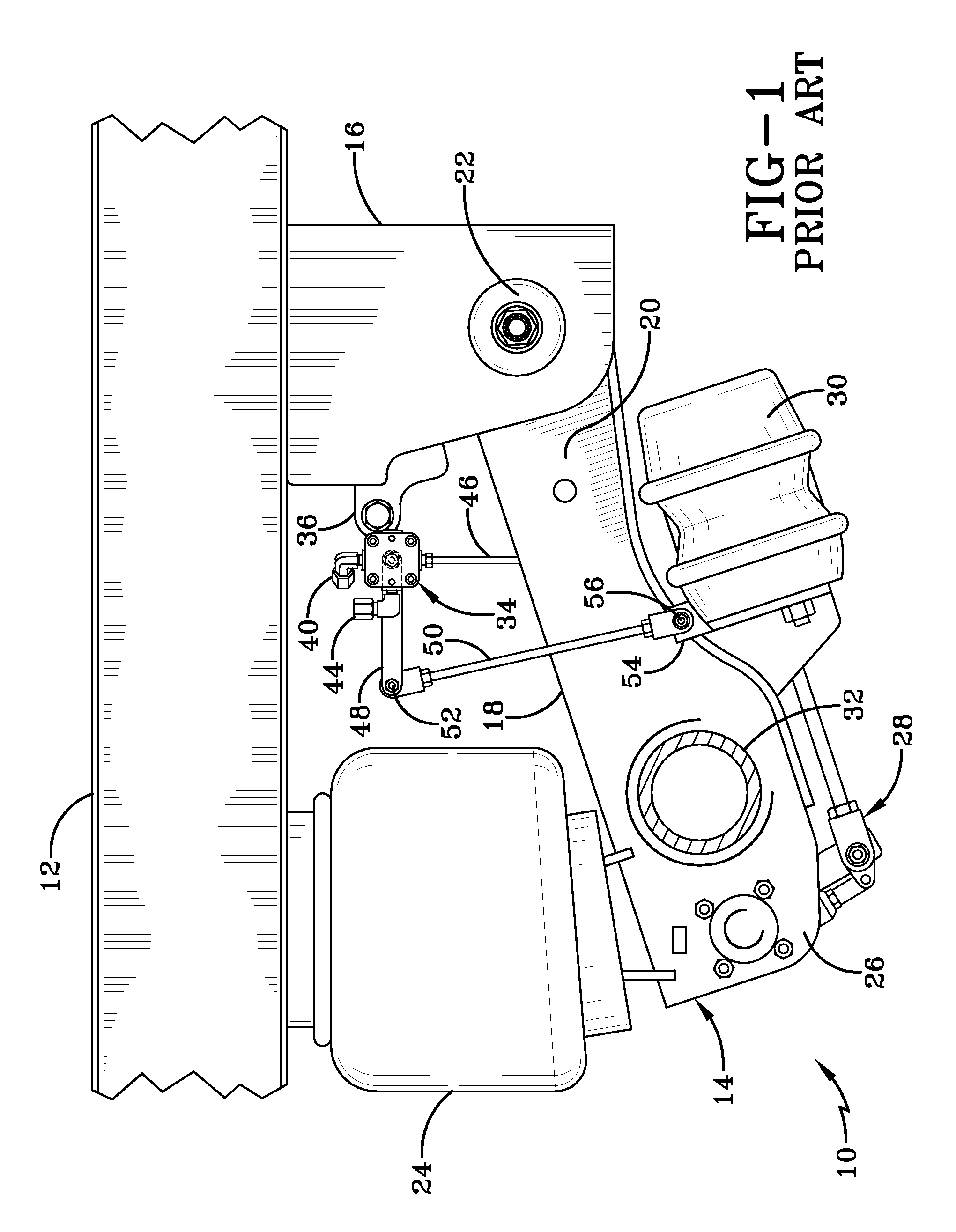
Conversely, when the vehicle is unloaded and the air springs of the axle / suspension system are extended, causing the vehicle frame to be positioned above design ride height or further away from the travel surface, air is exhausted from the air springs, thereby deflating / compressing them until the axle / suspension system lowers the vehicle frame to the design ride height.
Typically, these prior art pneumatic control systems exhaust all of the air from the air springs of the rear axle / suspension system.
Some problems associated with these prior art height control valves which are used in conjunction with pneumatic control systems that exhaust all of the air from the air springs of the rear axle / suspension system include difficulty on the part of the operator of the vehicle in determining when the rear axle / suspension system has become sufficiently exhausted so as to allow increased maneuverability of the vehicle.
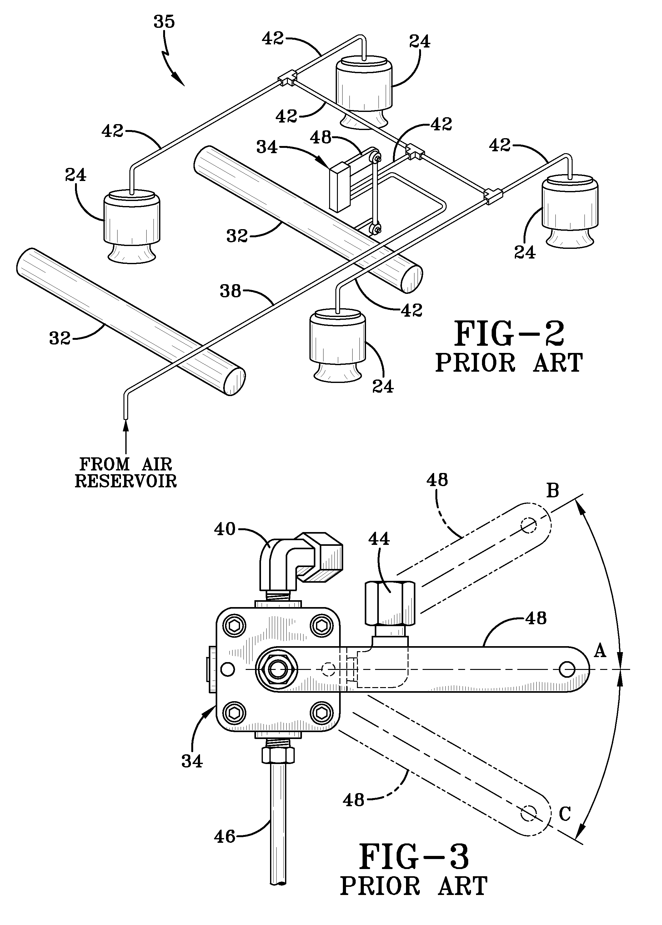
Another problem associated with such prior art valves and pneumatic control systems is relatively slow re-inflation of the air springs of the axle / suspension systems once the rear axle / suspension system dump control has been turned off.
The prior art height control valve does not have the capability to limit or stop the exhaustion of air from the rear air springs once a sufficient lowered ride height has been reached.
The amount of time required for the air springs of the front and rear axle / suspension systems to re-inflate can be quite lengthy because, once the solenoid valve is de-energized and the front and rear air springs reach equilibrium, the height control valve must re-inflate all of the air springs simultaneously.
As set forth above, this can take a relatively significant amount of time, the result being that the operator of the vehicle may drive for some time with the vehicle being non-air supported or below design ride height.
Operating the vehicle under these conditions potentially reduces axle / suspension system performance and longevity and might also lead to undesirable wear and possible premature failure of the components of the front and rear axle / suspension systems.
Typically, these prior art pneumatic control systems over-inflate the air springs of the front and rear axle / suspension systems until the shock absorbers physically stop the vehicle from being raised any further.
Some problems associated with these prior art height control valves which are used in conjunction with pneumatic control systems that over-inflate the air springs of the front and rear axle / suspension systems include potential damage to the shocks and shock mounts as they are not designed to react the full force exerted on them by the front and rear air springs during over-inflation.
Moreover, the air springs themselves can also be potentially damaged during the over-inflation because the air springs are not designed to be at high inflation pressures when fully extended.
A regulator could be utilized by the operator of the vehicle to control how much pressure is introduced into the air springs during over-inflation, but this operation is dependent upon the operator of the vehicle and can still lead to over-stressing the shocks, shock brackets and / or air springs.

Method used


Image

  • Multi-stage height control valve including position sensitive pilot signal and pressure boost for vehicle air springs
  • Multi-stage height control valve including position sensitive pilot signal and pressure boost for vehicle air springs
  • Multi-stage height control valve including position sensitive pilot signal and pressure boost for vehicle air springs

Examples


first embodiment

[0057]As set forth above, first embodiment multi-stage height control valve 100 includes both rotor valve portion 194 and boost valve 146, which will now be described. Turning to FIGS. 12 and 13, multi-stage height control valve 100 is shown schematically with rotor valve portion 194 and pilot boost valve 146. Pilot boost valve 146 of height control valve 100 is a two position, three way pilot valve well known to those having skill in the relevant art. Boost valve 146 includes a pilot port 174a which is piloted by an integrated load proportioning valve 166 via a boost pilot conduit 162. Pilot boost valve 146 is in fluid communication with pilot opening 132 (FIG. 6) and pilot port 134 via an internal pilot conduit 160. Boost valve 146 is also in fluid communication with air reservoir 66 via air reservoir conduit 38 and a boost conduit 192. A bleed conduit 164 is in fluid communication with secondary ride height conduit 102 and with atmosphere. Bleed conduit 164 allows pressure in sec...

second embodiment

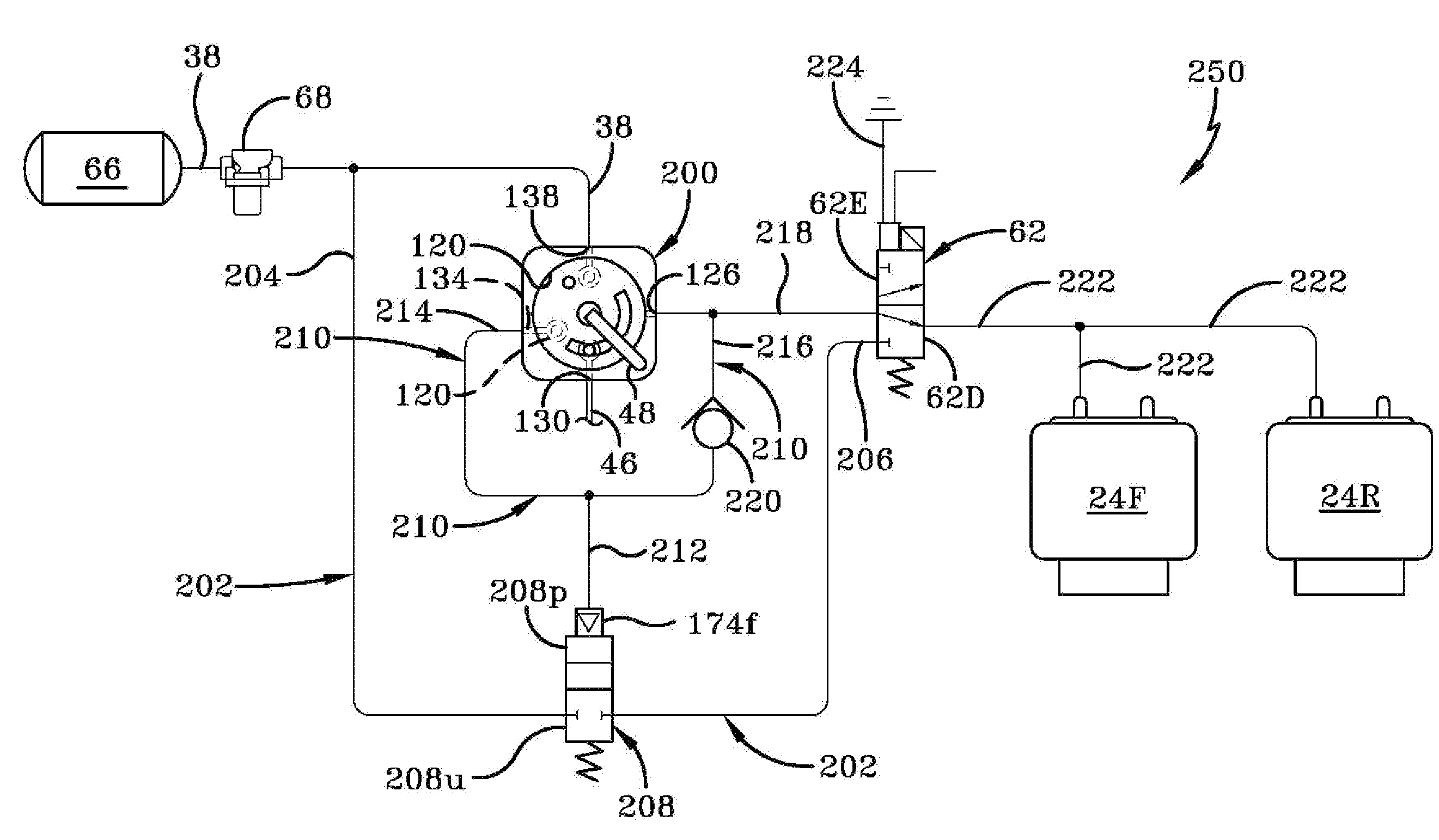
[0079]With continuing reference to FIG. 14, a key feature of second embodiment height control valve 200 of the present invention will now be described. When the operator of the vehicle desires to raise the ride height of the vehicle in order to provide greater ground clearance over high sections of the road surface, such as railroad tracks and off road conditions, the operator actuates a switch (not shown) which is electrically connected to solenoid valve 62, which in turn energizes the solenoid valve into its energized state 62E. In this state, air is routed from air reservoir 66, through air reservoir conduit 38, through first air spring conduit 202, through pilot valve 208, through the solenoid valve, through third air spring conduit 222, and into front and rear air springs 24F,R, thereby raising the vehicle ride height. As the vehicle raises, axle suspension system 10 articulates to an air spring extended position and the distance between vehicle frame 12 and beam 18 increases, ...


PUM


Abstract

A multi-stage height control valve for a pneumatic control system of a vehicle includes an air reservoir port, an exhaust port, an air spring port and a pilot port operatively connected to a rotor valve which is in turn operatively connected to the vehicle. The air reservoir port fluidly communicates with an air tank. The air spring port fluidly communicates with the air springs of the vehicle. The exhaust port opens to atmosphere. The pilot port fluidly communicates with a control / warning device such that, when a secondary ride height is reached by the vehicle, the pilot port signals the control / warning device in order to maintain the vehicle at the secondary ride height. The pilot port alternatively provides an air pressure boost in order to quickly re-inflate the air springs of the vehicle to return the vehicle to the primary design ride height.

Description

CROSS-REFERENCE TO RELATED APPLICATION[0001]This application claims the benefit of U.S. Provisional Application No. 61 / 025,930, filed on Feb. 4, 2008.BACKGROUND OF THE INVENTION[0002]1. Field of the Invention[0003]The invention relates generally to the art of air-ride axle / suspension systems for heavy-duty vehicles, such as tractor-trailers or semi-trailers, which cushion the ride and stabilize the vehicle during operation. More specifically, the invention relates to pneumatic control of the air springs of the air-ride axle / suspension systems, and in particular to a multi-stage height control valve for the air-ride axle / suspension systems which includes a position sensitive pilot signal that, for example, in one instance allows the height control valve to signal when a secondary ride height threshold has been reached to prevent further exhaustion of air from the air springs, and in another instance provides a pressure boost to relatively quickly re-inflate the air springs.[0004]2. D...

Claims


Application Information

Patent Timeline
Patent Type & Authority Applications(United States)
IPC IPC(8): F16K11/02
CPCB60G17/0525B60G2800/914B60G2300/026B60G2300/042B60G2400/252B60G2400/51222B60G2500/202B60G2500/2021B60G2500/2042B60G2500/2044B60G2500/30B60G2600/044B60G2600/07B60G2600/20B60G2600/26B60G2600/85B60G2800/204B60G2202/152Y10T137/86501Y10T137/86638
Inventor MORRIS, BRIAN R.CERVANTEZ, JESSE W.
Owner HENDRICKSON USA L L C
Learn More