
Image processing device and image processing method

a technology of image processing and image quality, applied in the field of image processing device and image processing method, can solve the problem that the same image quality cannot be achieved, and achieve the effect of low cos

Active Publication Date: 2009-08-06
CANON KK
View PDF7 Cites 12 Cited by
  • Summary
  • Abstract
  • Description
  • Claims
  • Application Information

AI Technical Summary

Benefits of technology

[0008]An image processing device in accordance with the present invention reduces gray levels of an image, and comprises a comparing unit configured to compare a pixel value of each pixel included in the image with a plurality of thresholds included in a threshold arrangement to reduce the levels of gray of the image, wherein part of the plurality of thresholds compared with the pixel value of a first pixel of the pixels agrees with part of the plurality of thresholds compared with the pixel value of a second pixel of the pixels.
[0011]According to the present invention, a low resolution printing engine unit can achieve an image quality close to that of a high resolution printing engine unit at low cost.

Problems solved by technology

However, when receiving a 600-DPI multilevel image and printing the image with an engine unit having a 600-DPI printing resolution, the same image quality cannot be achieved as when printing with a printing engine unit having a 1200-DPI printing resolution.

Method used


Image

  • Image processing device and image processing method
  • Image processing device and image processing method
  • Image processing device and image processing method

Examples


embodiment 1

[0038]In the following, a first embodiment in accordance with the present invention will be described in detail with reference to the accompanying drawings.

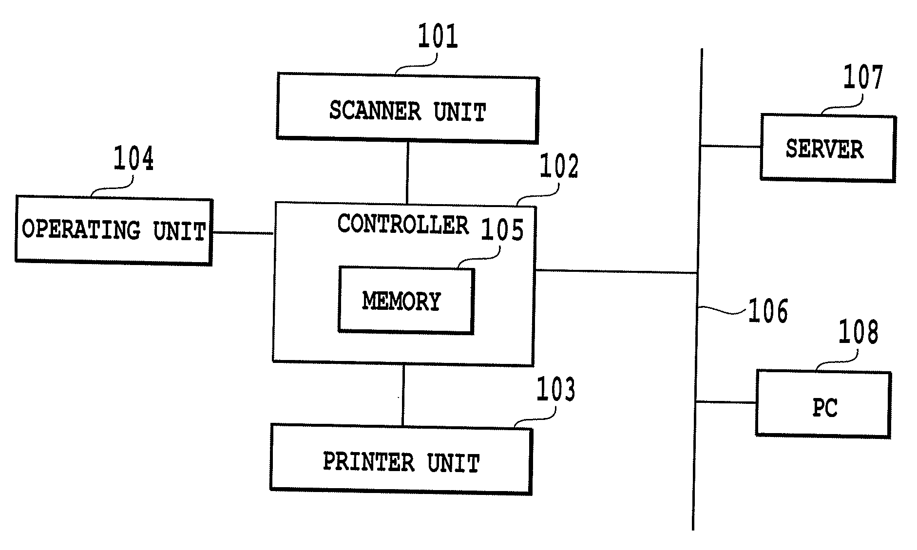
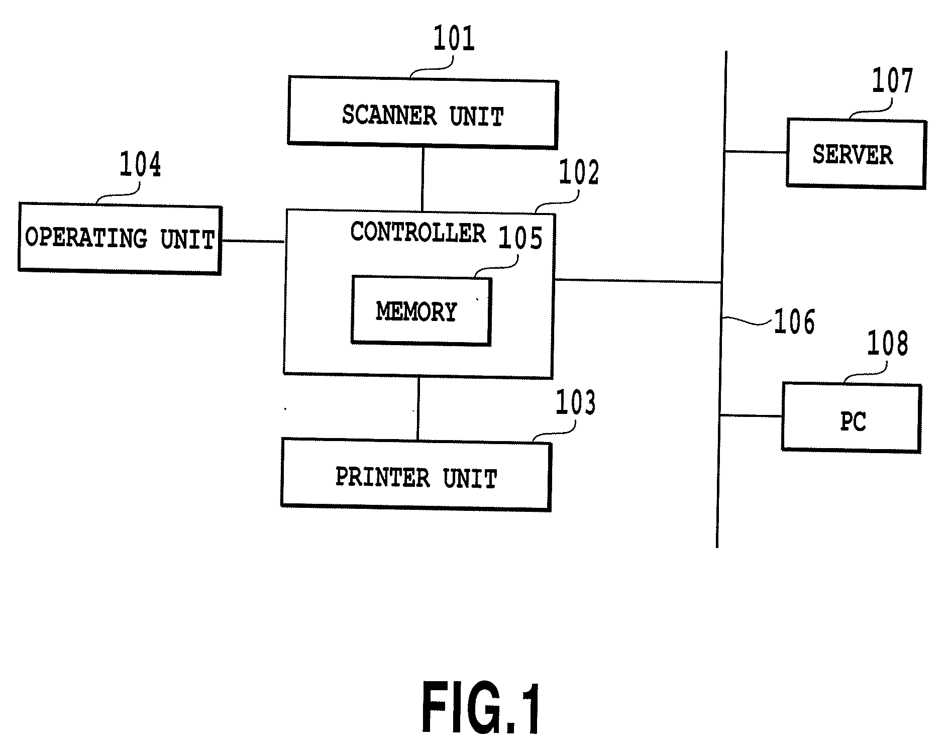
[0039]FIG. 1 is a schematic block diagram of a system comprising an image forming device (a digital multifunction machine such as COPY / PRINT / FAX, for example) to which the present invention is applicable, a server and a PC connected to the image forming device.

[0040]The image forming device of the present embodiment includes a scanner unit 101 for carrying out original document reading processing, and a controller 102 for performing image processing of an image read by the scanner unit 101 and for storing the image in a memory 105. In addition, the device includes an operating unit 104 for a user to set various printing requirements for the image read by the scanner unit 101.

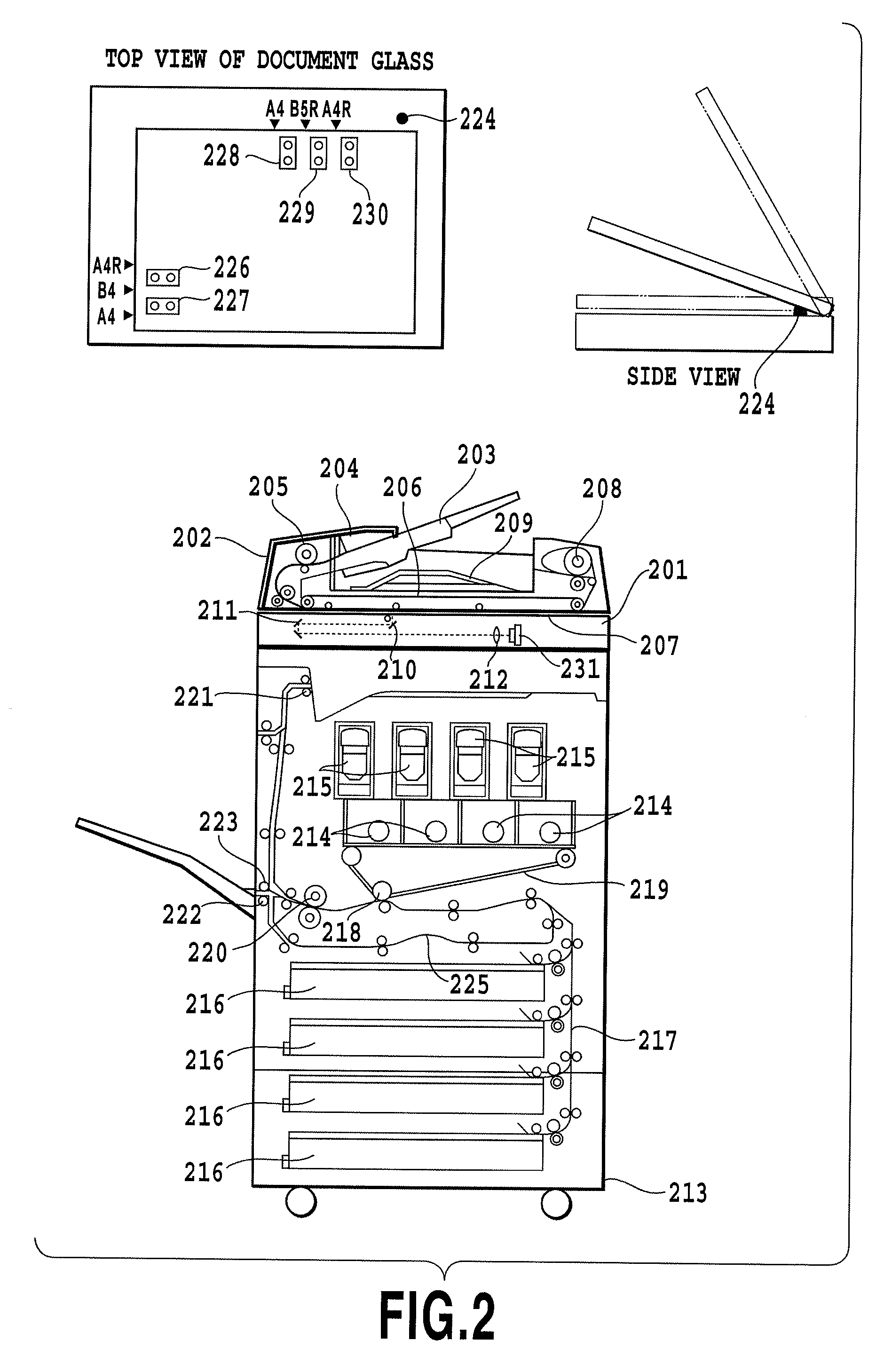
[0041]Furthermore, the device includes a printer unit 103 and the like for forming a visualized image on recording paper from the image data read out from th...

embodiment 2

[0101]Next, a second embodiment in accordance with the present invention will be described in detail with reference to the drawings.

[0102]In the foregoing embodiment 1, the resolution-enhancing dithering processing that employs the dithering method based on the rational tangent method is described. In the present embodiment, the high resolution dithering processing employing the dithering method based on the irrational tangent method will be described. In the present embodiment, the threshold acquiring unit 307 in the halftone processing unit 302 described in the embodiment 1 acquires a plurality of thresholds based on the irrational tangent method. As for the configuration other than that relating to the high resolution dithering processing employing the dithering method based on the irrational tangent method which will be described later, since it is the same as that of the foregoing embodiment 1, its description will be omitted here.

[0103]The processing of the halftone processing...


PUM


Abstract

A device capable of providing an image quality that is close to a high resolution printing engine unit by low resolution printing engine unit. It includes a processing unit for comparing thresholds included in a high resolution dithering matrix with a pixel value included in each pixel of a low resolution input image and for outputting multi-level gray scale signal values. In addition, the processing unit includes a comparing unit for comparing a pixel value of each pixel of the low resolution input image with a plurality of thresholds included in the high resolution dithering matrix; an integrating unit for obtaining for each pixel the multi-level gray scale signal value by integrating a plurality of comparison results obtained for each pixel; and an output unit for outputting the multi-level gray scale signal values obtained by the integrating unit.

Description

BACKGROUND OF THE INVENTION[0001]1. Field of the Invention[0002]The present invention relates to an image processing device and an image processing method relating to screen processing for generating a multilevel halftone image for forming halftone dots in accordance with an input multi-level gray scale image.[0003]2. Description of Related Art[0004]A known technique forms a 1200-DPI binary image by comparing each pixel of a 600-DPI multilevel image with four thresholds, and prints the image by use of a printing engine unit with a printing resolution of 1200 DPI (see Japanese Patent Laid-Open No. 2005-064954, for example).[0005]However, when receiving a 600-DPI multilevel image and printing the image with an engine unit having a 600-DPI printing resolution, the same image quality cannot be achieved as when printing with a printing engine unit having a 1200-DPI printing resolution.SUMMARY OF THE INVENTION[0006]The present invention provides an image processing device and method for a...

Claims


Application Information

Patent Timeline
IPC IPC(8): H04N1/40
CPCH04N1/405H04N1/40087H04N1/40H04N1/403H04N1/407
Inventor KASHIBUCHI, YOICHIKABURAGI, HIROSHI
Owner CANON KK
Learn More