Catheter Assembly

a catheter and assembly technology, applied in the field of catheters, can solve the problems of less tear resistance, and achieve the effect of reducing the total void space and facilitating the lengthening

Active Publication Date: 2009-08-06
WL GORE & ASSOC INC
View PDF98 Cites 32 Cited by
  • Summary
  • Abstract
  • Description
  • Claims
  • Application Information

AI Technical Summary

Benefits of technology

[0014]In an aspect of the invention, the thin covering or wrapping material is made from a thin tape of porous expanded polytetrafluoroethylene (ePTFE) that can be helically wrapped about the exterior of a catheter shaft. Most preferably, the wrapping is accomplished in two opposing directions parallel to the length of the catheter shaft, resulting in a bias-ply construction. This thin covering offers good transparency and is easily punctured by the end of a guidewire, and yet is resistant to tearing at the puncture site.
[0019]Other embodiments using the catheter shaft may be provided with a puncturable tubular form inserted into the slot. This tubular form may be made with filaments braided into the tubular form, or a tubular form made of helically wound filaments or from a thin polymeric material, with the tube having an inside diameter adequately large to accommodate a guidewire of the desired size. These tubes are fitted and secured into the slot formed into the catheter shaft, with the result that the outer surface of the braided or helically wound tube covers the exposed part of the slot and allows for the back end of a guidewire contained within the tube to be passed through any interstice between adjacent filaments of the braided or helically wound tube. When the tubular form is made from the thin polymeric material, the resulting tube inserted into the catheter shaft slot is puncturable at any desired location by the back end of a guidewire.
[0020]The ability of the catheter to be punctured by the back end of a guidewire at any desired location along the length of the puncturable section of the catheter allows the catheter assembly to be used effectively as desired in either OTW or RX mode.
[0022]By adjustable length is meant that the length of the adjustable length guidewire catheter lumen may be changed by the application of easily applied manual axial force. In its axially extended or fully lengthened state, the adjustable length guidewire catheter lumen is at least 10% longer than when in the axially compressed, fully shortened state. More preferably, the adjustable length guidewire catheter lumen is adjustable by an amount of at least about 20%, or 30%, or 40%, or 50%, or 75%, or 100%, or 200%, or 400%, or 1000%, or 2000%.
[0023]The adjustable length guidewire catheter lumen is adjustable in length by virtue of being scrunchable. This means that this tubular component is easily shortened in length under axial force, without telescoping as by the successive sliding of overlapped concentric tubular sections. Various means of providing a scrunchable tube for use as the adjustable length guidewire catheter lumen include the provision of corrugations (i.e., wrinkles, or accordion pleats or folds), or by the use of a porous tube that compresses axially by reduction in total void space. These are further described below.

Problems solved by technology

These materials may also offer good translucency, but may be less tear resistant than the helically wrapped ePTFE thin coverings.

Method used


Image

  • Catheter Assembly
  • Catheter Assembly
  • Catheter Assembly

Examples


Embodiment Construction

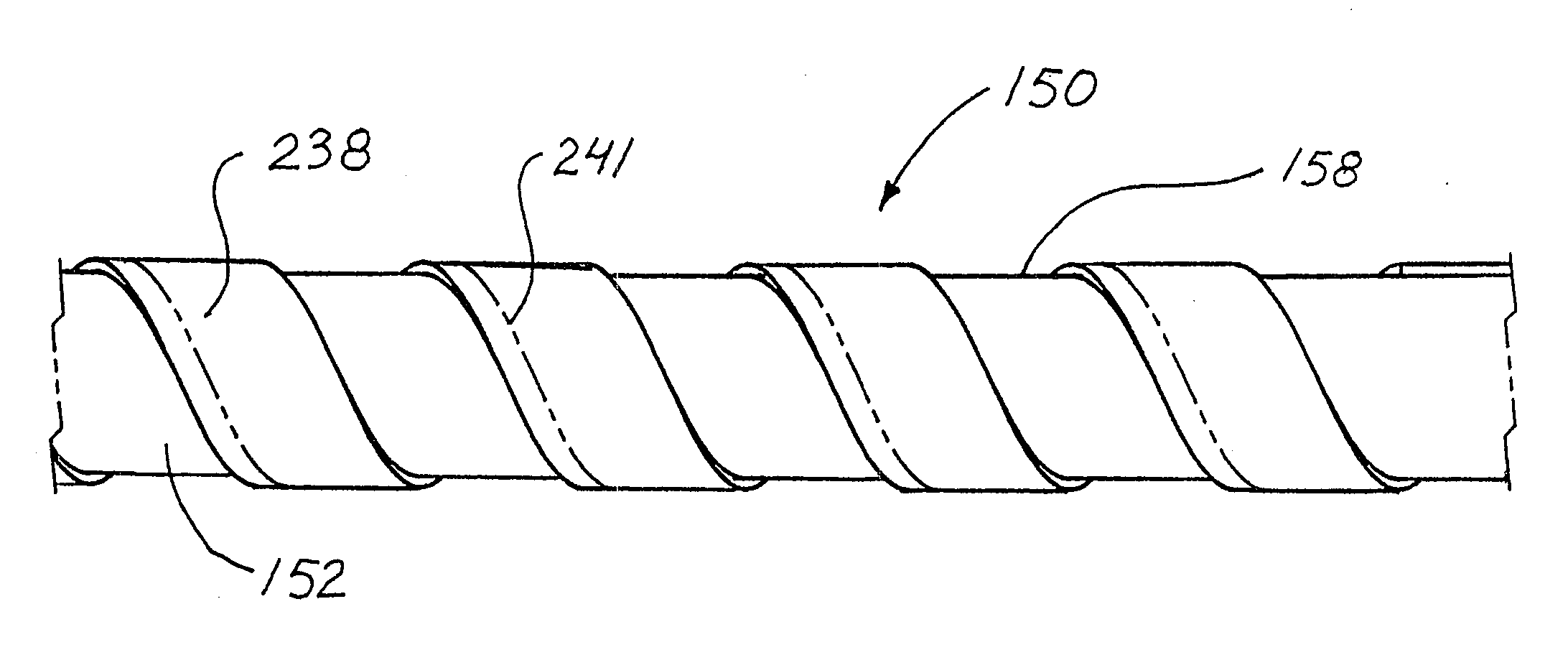
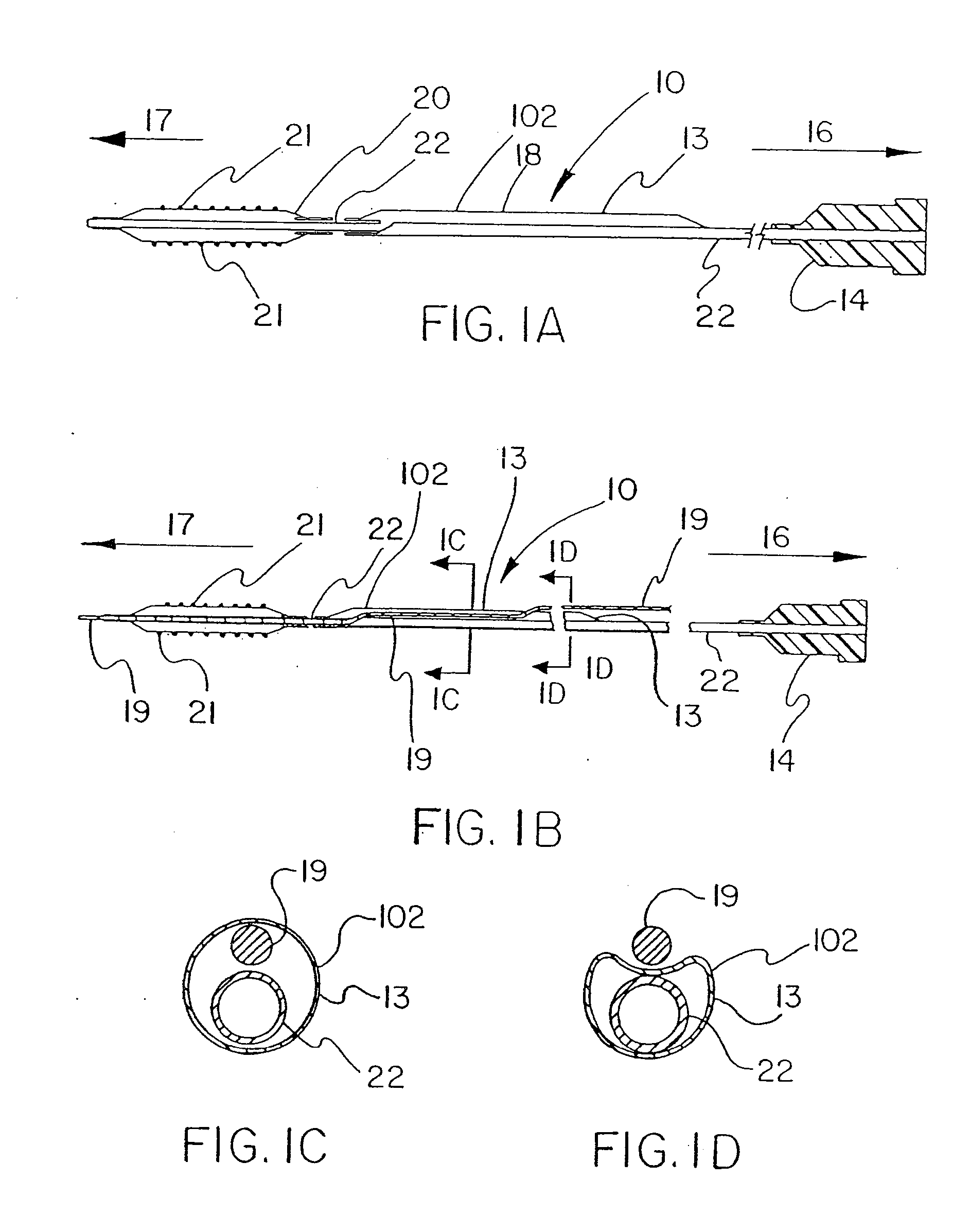
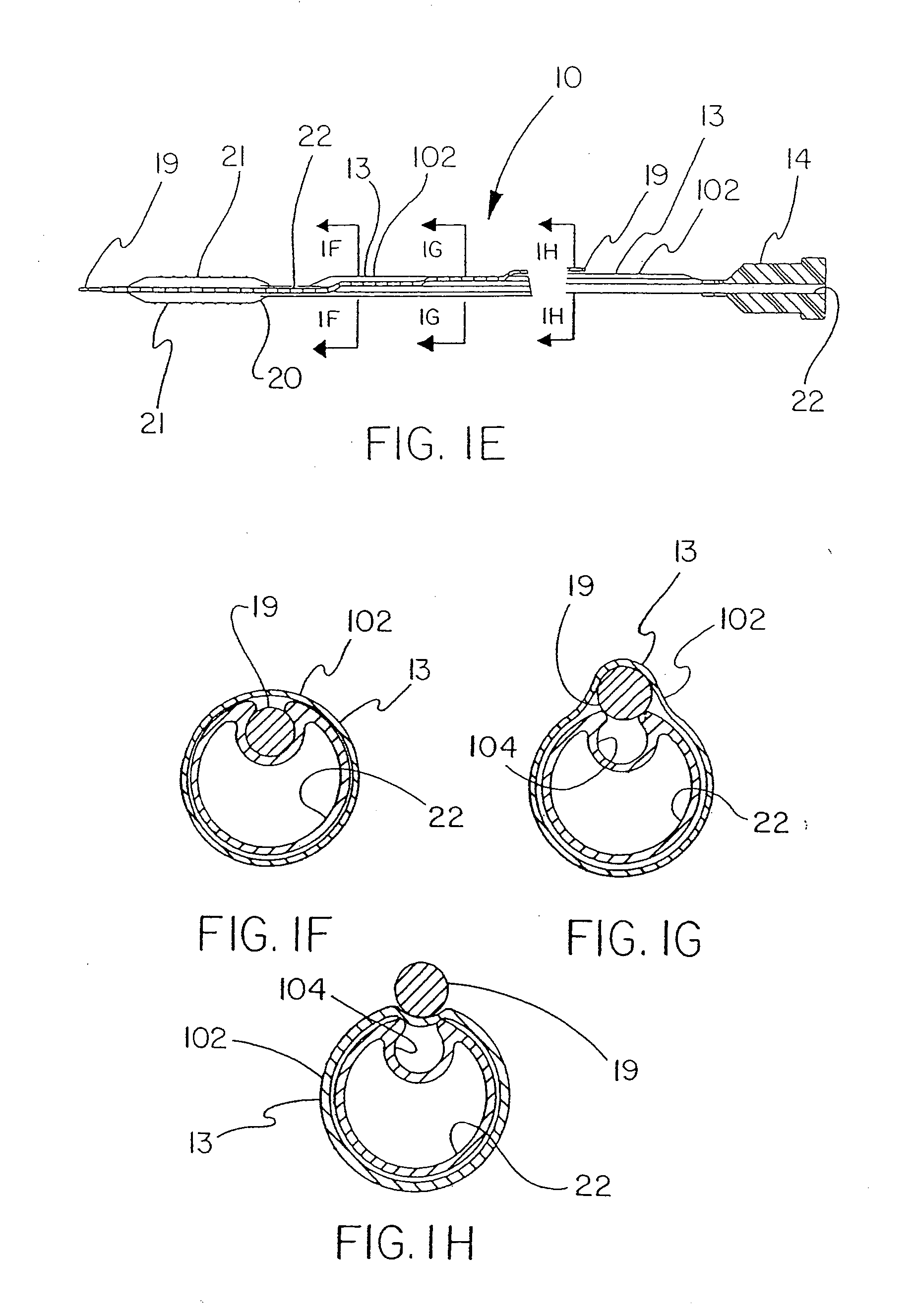
[0090]FIGS. 1A-1H describe a catheter 10 of the present invention provided with a thin, puncturable cover 102 over the guidewire lumen 18. Typically, catheter 10 may include devices such as a catheter balloon 20 and / or stent 21 at its distal end 17 and a hub 14 at the proximal end 16. As shown by FIGS. 1A-1H, the thin, puncturable cover 102, in this instance a thin-walled tubular sheath 13 (forming guidewire lumen 18) designed to be punctured by the back end of a guidewire 19 (or other suitable means), may be placed coaxially about the inflation lumen 22. The length of the thin tubular sheath 13 may extend over all or part of the length of catheter shaft.

[0091]After feeding guidewire 19 through the distal section of the guidewire lumen 18 and into the thin-walled tubular sheath 13, the physician may choose any desired location along the length of thin-walled tubular sheath 13 at which to puncture the thin, puncturable cover 102 with the guidewire 19. In this fashion the physician ma...


PUM


Abstract

Novel catheter constructions comprising thin covering or wrapping materials such as polymer films. A catheter provided with a guidewire catheter lumen having a thin covering that is easily punctured by a guidewire at virtually any desired point along the catheter length. The thin covering may be integral with the catheter shaft, or may be a separate component that covers only the portion of the catheter shaft immediately adjacent the outer portion of the guidewire lumen, or may be a thin tubular construct that surrounds the entire catheter shaft. Moreover, polymer film can be used in combination with one or more elements to produce novel catheter constructions.

Description

CROSS REFERENCE TO RELATED APPLICATIONS[0001]This application is a continuation of U.S. patent application Ser. No. 11 / 500,836, filed Aug. 7, 2006, which is a continuation-in-part of U.S. patent application Ser. No. 10 / 895,817, filed Jul. 21, 2004, and now abandoned, which is a continuation-in-part of U.S. patent application Ser. No. 10 / 402,083, filed Mar. 28, 2003, which is a continuation-in-part of U.S. patent application Ser. No. 10 / 346,977 filed Jan. 17, 2003.FIELD OF THE INVENTION[0002]The present invention relates to the field of catheters. More particularly, the invention relates to catheters intended for the delivery to a patient of, for example, therapeutic agents or devices.BACKGROUND OF THE INVENTION[0003]A variety of different therapies can be delivered within the human body by catheter devices. Therapeutic devices such as dilation balloons, occlusion balloons, thrombectomy treatment devices, stents, and embolic filters, and therapeutic agents such as drugs and radiation...

Claims


Application Information

Patent Timeline
Patent Type & Authority Applications(United States)
IPC IPC(8): A61M25/00
CPCA61M25/0052A61M25/0051A61M25/10A61M25/1002A61M25/1011A61M2025/0034A61M2025/0035A61M2025/0063A61M2025/0183A61M2025/0188A61M2025/1056A61M2025/1081A61F2/958A61M25/0023A61M25/0029A61M25/0032A61M25/0043A61M25/005A61M25/0053
Inventor CAMPBELL, CAREY V.CULLY, EDWARD H.ESKAROS, SHERIFFOUTRAKIS, GEORGE N.MANN, JAMES WILLIAMROEBER, PETER J.TRAPP, BENJAMIN M.VONESH, MICHAEL J.
Owner WL GORE & ASSOC INC
Why Eureka
Try Eureka