Electric roman shade

a technology of roman shade and electric motor, which is applied in the direction of shutter/movable grille, door/window protective device, curtain suspension device, etc., to achieve the effect of retaining a tidy appearance and increasing the convenience of us

Inactive Publication Date: 2009-08-13
BIN TERNG ENTERPRISE
View PDF7 Cites 39 Cited by
  • Summary
  • Abstract
  • Description
  • Claims
  • Application Information

AI Technical Summary

Benefits of technology

[0006]Therefore, the object of the present invention is to provide an electric roman shade which sequentially and steadily transports cord without imparting a manual force so as to increase convenience of using and retain a tidy appearance of the sheet.
[0007]The electric roman shade in accordance with the present invention mainly provides with a head rail, a covering sheet, a transmission apparatus and a controlling mechanism. Particularly, the transmission apparatus has a roller bar in the rail, a power motor disposed thereon for driving the bar and cord spools periodically spaced on the bar; each cord spool has a revolving shaft with threads thereon and a cord convolved thereon, thereby steadily and smoothly outputting the cord to descend or lift the covering sheet. Furthermore, the controlling mechanism, which comprises a receiver, a controller attached thereto, and a limiter electrically engaged to the controller, assists to automatically motivate the motor and the bar and then rotate the cord spool in order to prevent the conventional manual method and efficiently increase the using convenience.

Problems solved by technology

Nevertheless, the conventional shade 1 requires a manual operation and probably results in the interruption of the spools 16 if imparting an uneven pulling to cord control 43, thus it is inconvenient.

Method used


Image

  • Electric roman shade
  • Electric roman shade
  • Electric roman shade

Examples


Embodiment Construction

[0018]Before describing in greater detail, it should note that the like elements are denoted by the similar reference numerals throughout the disclosure.

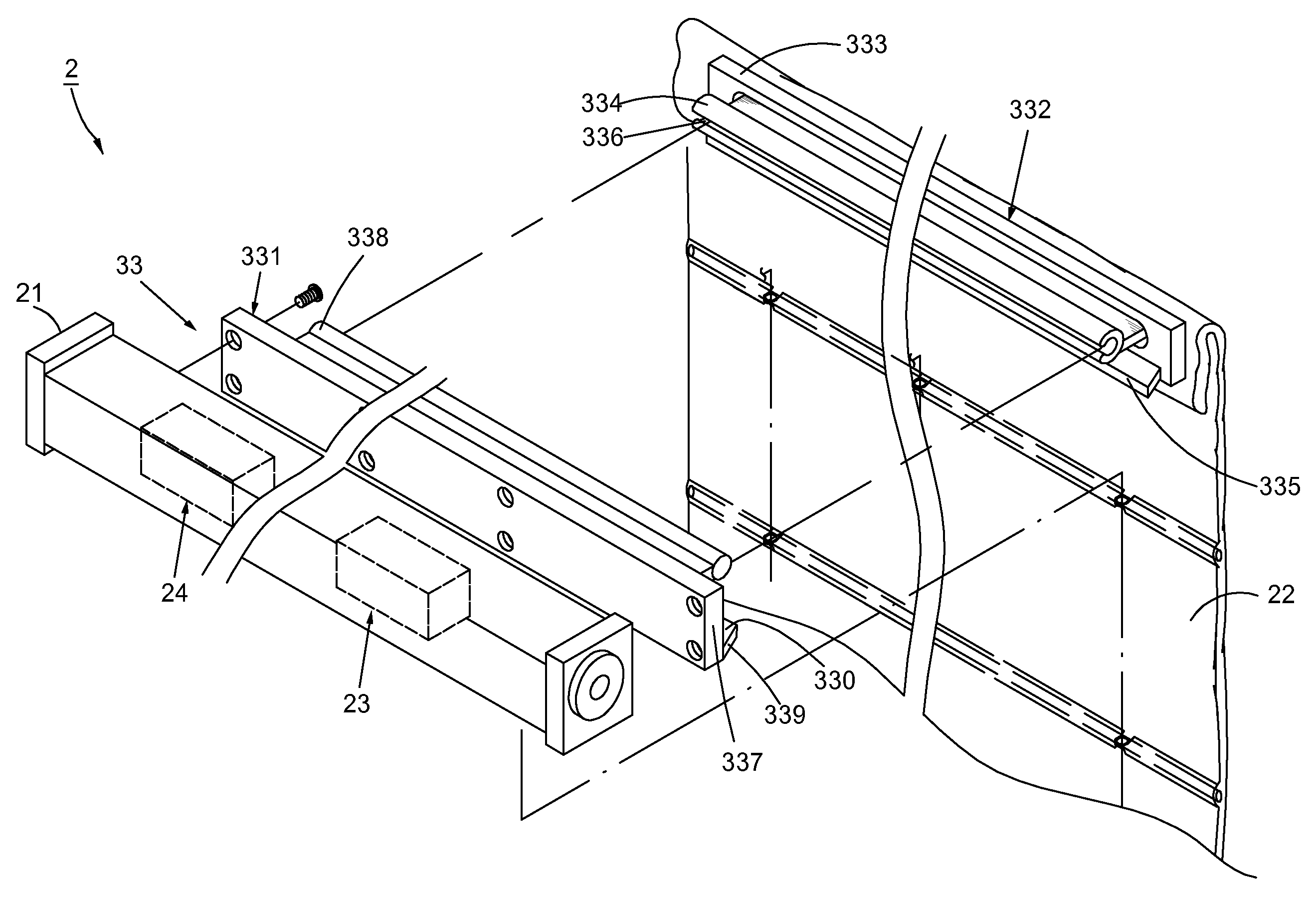
[0019]Referring to FIGS. 3 and 4, an electric roman shade 2 of the first preferred embodiment is comprised of a head rail 21, a covering sheet 22 secured to the rail 21, a transmission apparatus 23 disposed inside the rail 21 and a controlling mechanism 24 for driving the transmission apparatus 23; wherein, the head rail 21 has an inner space 211 therein, and the covering sheet 22 with one end thereof is fastened to the rail 21 and a bottom rail 221 is formed at the other end thereof.

[0020]Continuing with the aforementioned, the transmission apparatus 23 includes a roller bar 231 mounted in the inner space 211, a power motor 232 secured to the bar 231 and more than one cord spool 233 equidistantly spaced on the bar 231; wherein, a planetary gear assembly 238 (more definitely shown in FIG. 4) is located between the power motor 232 an...


PUM


Abstract

The present invention pertains to an electric roman shade mainly utilizing the controller to rotate the power motor and the roller bar, thus motivating the covering sheet upward and downward. Additionally, by means of the revolving shaft having threads disposed thereon, the cord thus sequentially wraps the shaft without overlapping thereby steadily adjusting movements of the sheet. Further, the covering sheet would automatically stop working while the sliding sections touching the switching tabs, and users can also rise and descend the sheet at desired positions, thus increasing the convenience of using.

Description

BACKGROUND OF THE INVENTION[0001]1. Field of the Invention[0002]The present invention relates to a window covering design, in particular to an electric roman shade.[0003]2. Description of the Related Art[0004]Referring to FIG. 1, a conventional roman shade 1 comprises a head rail 11, a pleated sheet 12 with one end affixed to the rail 11 and a transmission device 13 for driving the sheet 12; wherein, the rail 11 has an inner space 111 therein and an interlocking surface 14 secured to the front side thereof (as shown in FIG. 2), further a loop and hook strip 121 is attached to the upper edge of the sheet 12 for being adhesive to the interlocking surface 14. Additionally, the transmission device 13 consists of a roller bar 131 located in the space 111, a rolling pulley 133 attached to the bar 131, a cord control 132 arranged round the pulley 133, and a plurality of cord spools 16 equidistantly spaced on the bar 131, each of which further comprises a base 161 fastened to the bar 11, a ...

Claims


Application Information

Patent Timeline
IPC IPC(8): E06B9/68A47H5/00
CPCA47H2201/02E06B2009/2622E06B9/262
Inventor YEH, WEI-CHENG
Owner BIN TERNG ENTERPRISE
Why Eureka
Try Eureka