Battery operated cordless vibratory

a battery operated, cordless technology, applied in vibration drilling, drilling machines and methods, construction, etc., can solve the problems of dangerous electrical wires leading to the vibro, inability to operate an electrical machine, and need for electricians full time on the job, so as to achieve convenient and quick replacement

Inactive Publication Date: 2009-08-13
AMERICAN PILEDRIVING EQUIP
View PDF23 Cites 0 Cited by
  • Summary
  • Abstract
  • Description
  • Claims
  • Application Information

AI Technical Summary

Benefits of technology

[0014]Pictures of an exemplary embodiment of a cordless vibro are attached to the provisional application to which this application claims priority and which has been incorporated by reference into this application. As will be appreciated by those skilled in the art, there are a variety of different advantages of using a cordless vibro, including but not limited to: 1) the use of one or more electric motors powered by rechargeable batteries; 2)

Problems solved by technology

The electrical wires leading to the vibro were dangerous, sparking on steel piles and causing shorts and the need for electricians full time on the job.
The hydraulic machines could also go underwater, which was impossible for an electrical machine.
However, in either case, hydraulic or electric, there are still wires or hoses leading to the vibro from the power unit.
These wires or hoses create problems.
The maximum the crane operator can reach before relocation of the power unit is limited by the length of hoses.
Thus, time is often wasted at the job site while the workers are hassled with moving the hoses.
Further, as hoses are added to the system, horsepower and efficiency is decreased.
The hoses are a constant cause of failure due to damage.
Replacing the hoses is a danger because it is difficult to fix a damaged hydraulic hose in job site conditions without introducing dirt into the system while changing or fixing the broken lines.
The hoses may also twist up and cause more problems.
The hoses are expensive and require special fittings that vary in size and type, causing unwanted downtime as the mechanic searches for the correct type of fitting: There are a variety of differe

Method used


Image

  • Battery operated cordless vibratory
  • Battery operated cordless vibratory
  • Battery operated cordless vibratory

Examples


Embodiment Construction

[0021]The presently preferred embodiments of the present invention will be best understood by reference to the drawings, wherein like parts are designated by like numerals throughout. It will be readily understood that the components of the present invention, as generally described and illustrated in the figures herein, could be arranged and designed in a wide variety of different configurations. Thus, the following more detailed description of the embodiments of the present invention, as represented in the drawing(s), is not intended to limit the scope of the invention, as claimed, but is merely representative of presently preferred embodiments of the invention.

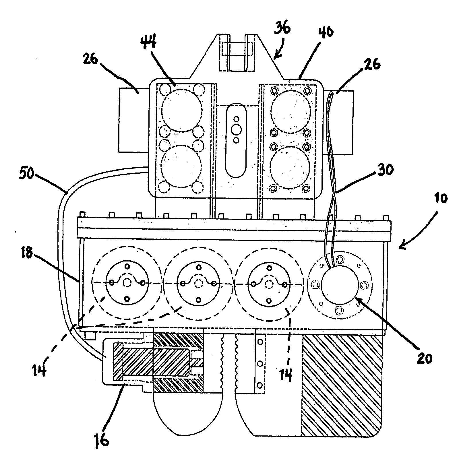
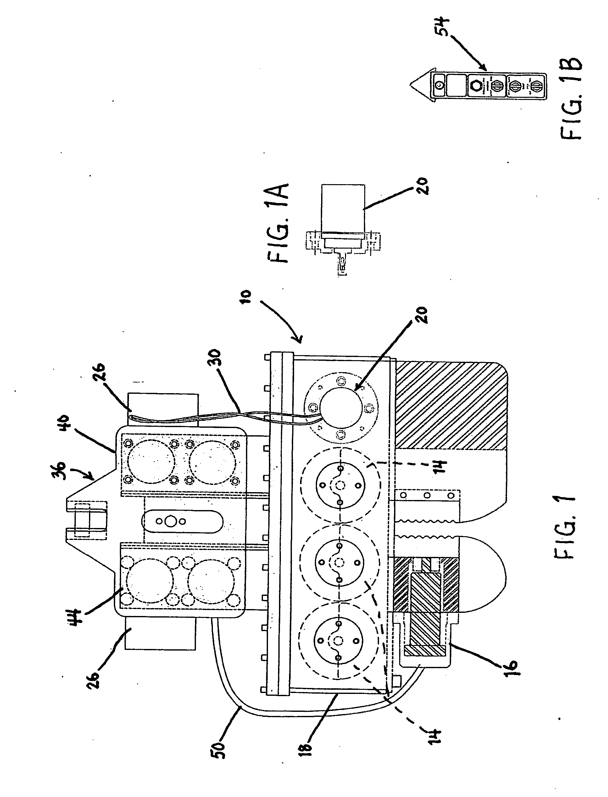
[0022]FIG. 1 is a schematic that illustrates a cordless vibratory hammer 10 (also called the vibro 10) that may be used to drive a pile. As with other types of vibratory hammers, the vibro 10 includes eccentrics 14 that will rotate and will produce force sufficient to drive a pile. The eccentrics 14 may be housed within a ge...


PUM


Abstract

A cordless vibratory pile driver (“vibro”) may use one or more batteries to provide the requisite power. The cordless vibro may sit in a stand that also recharges the unit while it is in the stand when the device is not in use. The replaceable batteries are mounted as part of the suppressor housing on top of the housing that contains the eccentrics. The batteries are balanced on both sides to distribute the weight evenly. A small battery powered electric hydraulic pump sits in the suppressor housing to provide oil to open and close the jaws. A digital hand held remote control sends the necessary signals to the machine to open and close the jaw and to start and stop the vibration.

Description

CROSS-REFERENCED RELATED APPLICATIONS[0001]This patent application claims the benefit of U.S. Provisional Patent Application Ser. No. 61 / 016,056 that was filed on Dec. 21, 2007, for an invention titled, BATTERY OPERATED CORDLESS VIBRATORY. Such provisional application is expressly incorporated herein by this reference.BACKGROUND OF THE INVENTION[0002]A vibratory pile driver (which is sometimes called a “vibro”) is a machine that is used to drive piles as part of deep foundation construction jobs. Typical examples of vibros are disclosed in U.S. Pat. No. 5,609,380, U.S. Pat. No. 5,117,925, and U.S. Pat. No. 5,263,544. These patents are expressly incorporated herein by reference.[0003]Currently, all vibros on the market today are either powered by a hydraulic power pack with long hoses leading to the hydraulic motor on the vibro, or they are powered by a power unit that is diesel engine over electrical generator (electric wires leading to vibro).[0004]The Russians invented the first e...

Claims


Application Information

Patent Timeline
IPC IPC(8): E02D7/18
CPCE02D7/18
Inventor WHITE, JOHN L.
Owner AMERICAN PILEDRIVING EQUIP
Why Eureka
Try Eureka