
Regenerative braking apparatus

a regenerative braking and apparatus technology, applied in the direction of motor/generator/converter stopper, dynamo-electric converter control, dc-ac conversion without reversal, etc., can solve the problems of falling in the reliability of an entire system, uneven operation levels of the respective regenerative braking apparatus, etc., and achieve the effect of falling in the reliability of the entire apparatus

Inactive Publication Date: 2009-08-13
MITSUBISHI ELECTRIC CORP
View PDF2 Cites 6 Cited by
  • Summary
  • Abstract
  • Description
  • Claims
  • Application Information

AI Technical Summary

Benefits of technology

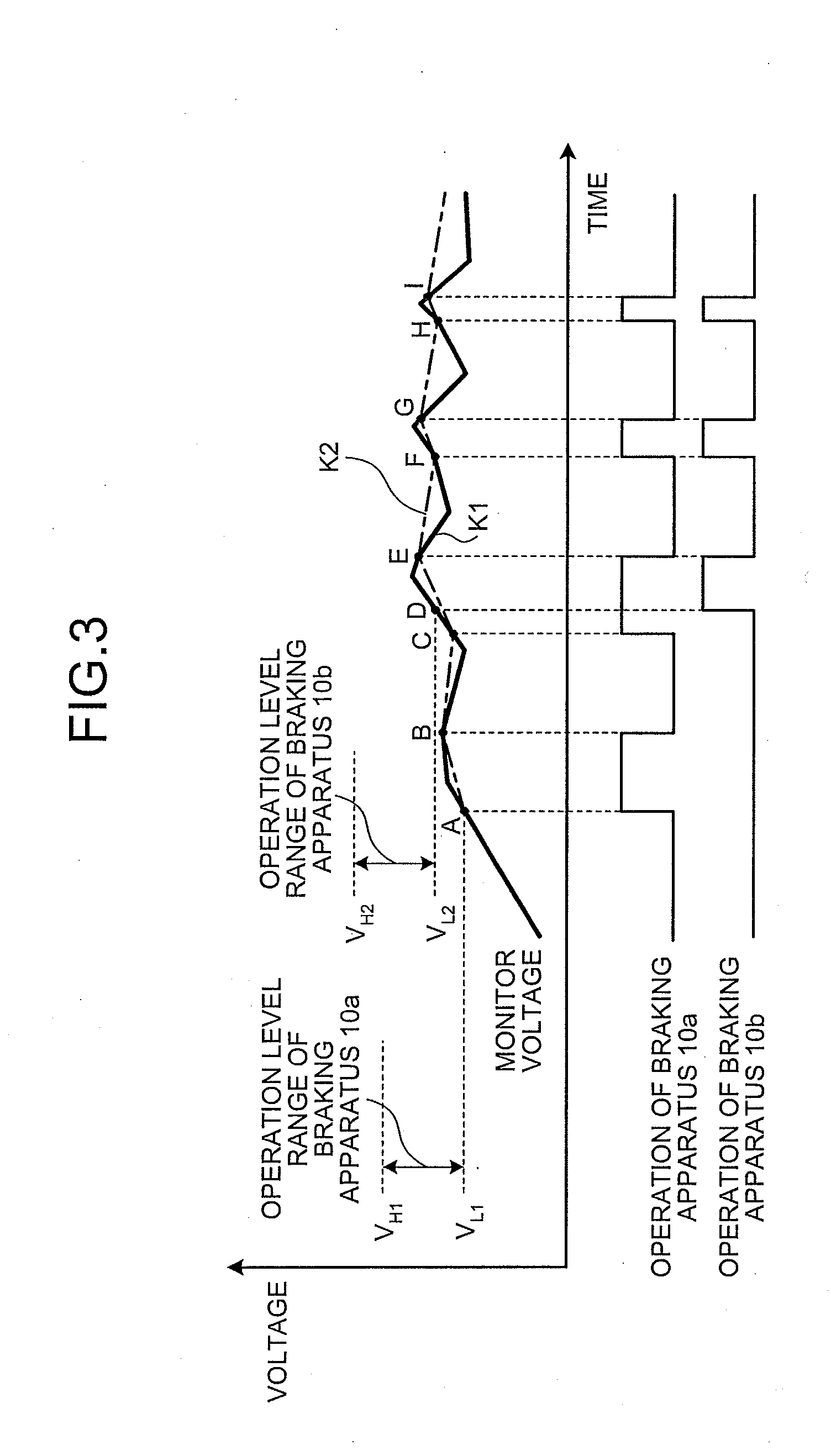
[0008]With the regenerative braking apparatus according to the present invention, when a plurality of regenerative braking apparatuses is connected to the power supply apparatus, based on a result of comparison between an operation level calculated according to energization time of a regenerative braking apparatus that consumes regenerative power and a monitor output obtained by monitoring the regenerative power, the energization time for the regenerative braking apparatus is controlled. Therefore, there is an effect that, even when the operation levels of the respective regenerative braking apparatuses are not uniform because of component tolerance or the like, it is possible to uniformly actuate the apparatuses, it is unnecessary to connect the apparatuses using control lines or the like, and a fall in reliability of the entire apparatus is not brought about.

Problems solved by technology

When a plurality of regenerative braking apparatuses is connected in parallel to a power supply apparatus such as an inverter apparatus, operation levels of the respective regenerative braking apparatuses are not uniform because of component tolerance or the like.
In particular, when the nonuniformity of the operations occur among such regenerative braking apparatuses, deterioration in components of the regenerative braking apparatus on which the operations concentrate progresses rapidly, leading to a fall in reliability of an entire system.

Method used


Image

  • Regenerative braking apparatus
  • Regenerative braking apparatus
  • Regenerative braking apparatus

Examples


first embodiment

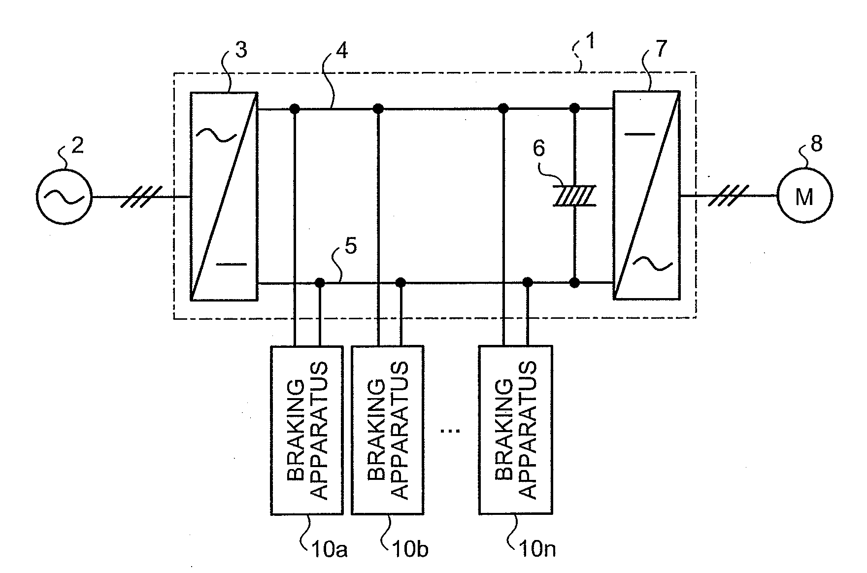
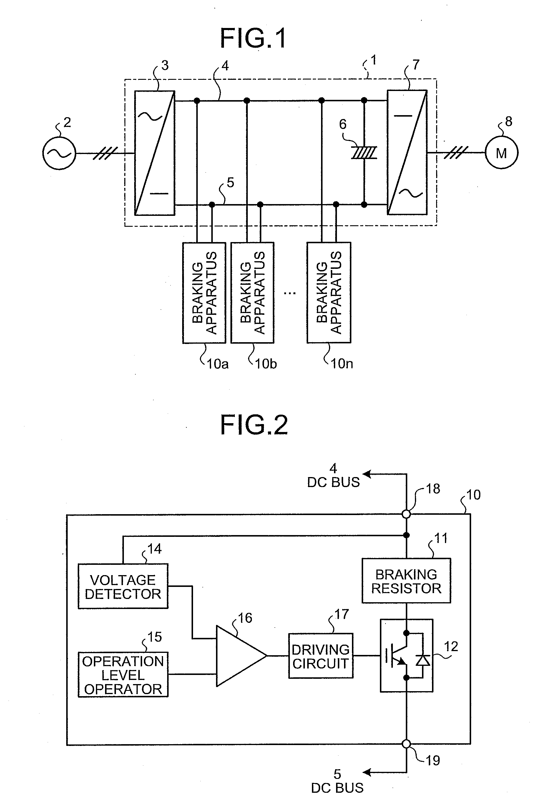
[0029]FIG. 1 is a diagram of a connection configuration of regenerative braking apparatuses according to a preferred embodiment of the present invention. In FIG. 1, an inverter apparatus 1 includes a converter unit 3 that is connected to an AC power supply 2, which is, for example, a three-phase AC power supply, and converts AC power of the AC power supply 2 into DC power, a smoothing capacitor 6 connected to an output side of the converter unit 3, and an inverter unit 7 that reconverts the DC power output from the converter unit 3 into AC power having a variable voltage and a variable frequency. A driving motor 8 that is driven by, for example, three-phase AC power is connected to an output terminal of the inverter apparatus 1, i.e., an output terminal of the inverter unit 7. A plurality of braking apparatuses (regenerative braking apparatuses) 10 (10a, 10, . . . , 10n) is connected in parallel between a pair of DC buses 4, 5 that connect the converter unit 3 and the inverter unit ...


PUM


Abstract

In a regenerative braking apparatus that is connected to a power supply apparatus that supplies electric power to a load, and consumes regenerative power regenerated from a load side together with other regenerative braking apparatuses that are connected to the power supply apparatus, an operation-level changing unit calculates, as occasion demands, according to energization time of a consuming unit, a lower limit of an operation level for judging whether an energizing unit should be actuated and changing and outputting the calculated lower limit of the operation level, a comparing unit compares the lower limit of the operation level output from the operation-level changing unit and a monitor output of a monitoring unit, and the energizing unit operates when the monitor output exceeds the lower limit of the operation level by a driving unit.

Description

TECHNICAL FIELD[0001]The present invention relates to a regenerative braking apparatus that is connected to a power supply apparatus such as an inverter apparatus that supplies electric power to a load, and that consumes regenerative power regenerated from the load side.BACKGROUND ART[0002]When a plurality of regenerative braking apparatuses is connected in parallel to a power supply apparatus such as an inverter apparatus, operation levels of the respective regenerative braking apparatuses are not uniform because of component tolerance or the like. Therefore, a situation in which operations concentrate only on a part of the regenerative braking apparatuses occurs. In particular, when the nonuniformity of the operations occur among such regenerative braking apparatuses, deterioration in components of the regenerative braking apparatus on which the operations concentrate progresses rapidly, leading to a fall in reliability of an entire system. Therefore, it is necessary to prevent th...

Claims


Application Information

Patent Timeline
IPC IPC(8): H02P3/22
CPCH02P3/22H02P3/18H02P27/06H02M7/48
Inventor NAGATAKI, YOSHIHIRO
Owner MITSUBISHI ELECTRIC CORP
Learn More