Method and apparatus to generate system clock synchronization pulses using a pll lock detect signal

Active Publication Date: 2009-08-13
ORACLE INT CORP
View PDF25 Cites 6 Cited by
  • Summary
  • Abstract
  • Description
  • Claims
  • Application Information

AI Technical Summary

Benefits of technology

[0009]Embodiments of the present invention provide methods and systems for generating clock synchronization pulses, indicative of an upcoming system clock cycle, using a Phase Locked Loop (PLL) lock detect signal. The PLL lock detect signal is generated when the internally generated clock by the Voltage Controlled Oscillator (VCO) is phase-aligned, also called locked, with the extern

Problems solved by technology

However, these clksync signals are irrelevant if the system and the internal clocks are n

Method used


Image

  • Method and apparatus to generate system clock synchronization pulses using a pll lock detect signal
  • Method and apparatus to generate system clock synchronization pulses using a pll lock detect signal
  • Method and apparatus to generate system clock synchronization pulses using a pll lock detect signal

Examples


Embodiment Construction

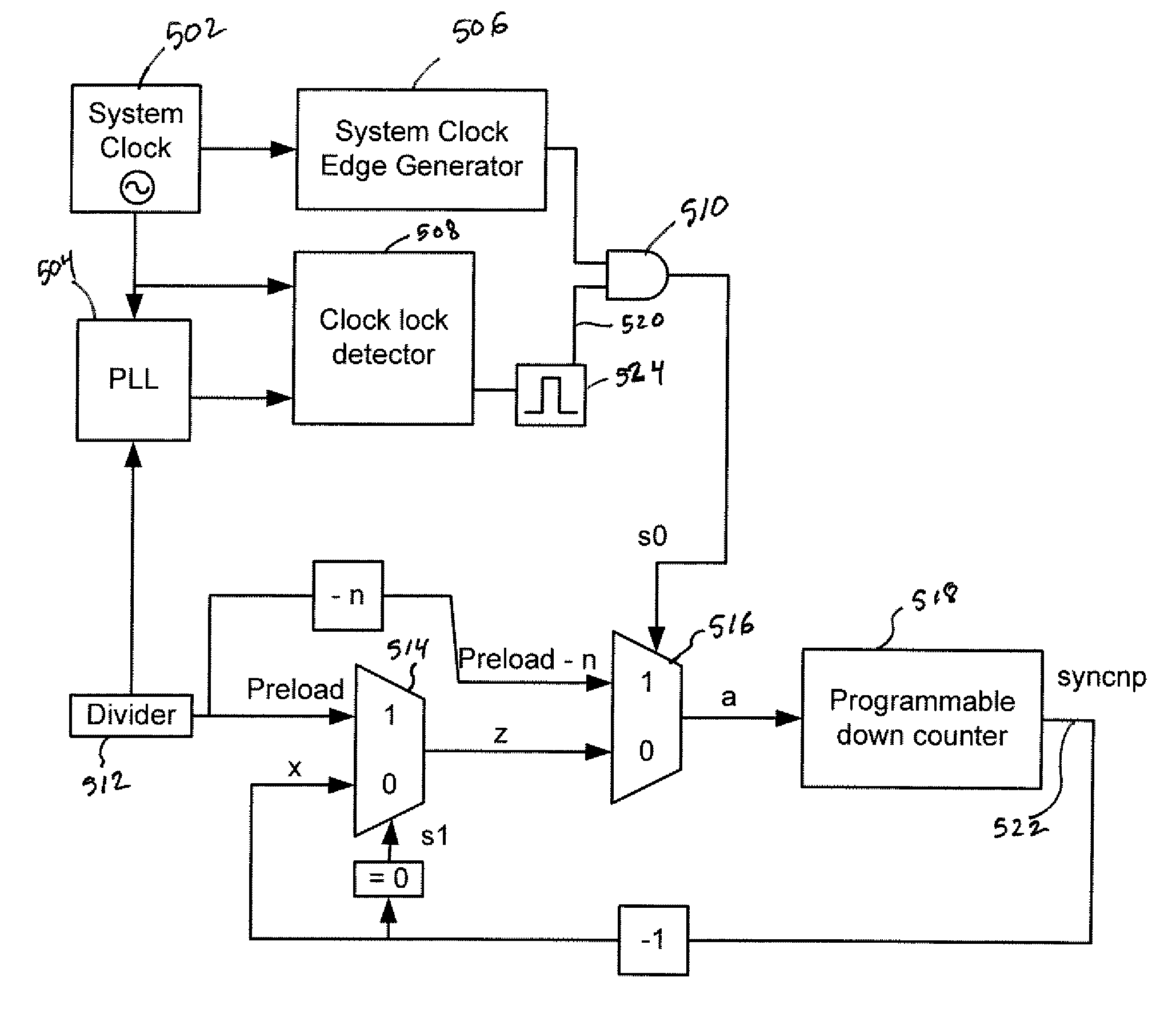
[0022]Method and apparatus for generating system clock synchronization pulses using a Phase Locked Loop (PLL) lock detect signal are provided. The method includes generating a clock lock detect, or pll_lock_detect, signal indicative that a system clock is synchronized with an internal clock, and determining an initial count value. Then, start counting beginning at a first rising edge of the system clock after the clock lock detect signal is generated, the counting starting with the initial count value. The method further includes generating a synchronization pulse (syncnp) when the counting ends, where the syncnp indicates the beginning of the next system clock cycle after n internal clock cycles, and continue generating syncnps separated by one system clock cycle so as to continue indicating the beginning of the next system clock cycle.

[0023]These syncnp signals are always in the same relative internal clock cycle relative to the system clock rising edge. The second ‘n’ in ‘syncnp’...


PUM


Abstract

Method and apparatus for generating system clock synchronization pulses using a Phase Locked Loop (PLL) lock detect signal are provided. The method includes utilizing a clock lock detect signal indicative that a system clock is synchronized with an internal clock, and determining an initial count value. Then, start counting beginning at a first rising edge of the system clock after the clock lock detect signal is generated, the counting starting with the initial count value. The method further includes generating a synchronization pulse (syncnp) when the counting ends, where the syncnp indicates the beginning of the next system clock cycle, and continue generating syncnps separated by one system clock cycle so as to continue indicating the beginning of the next system clock cycle. The method further guarantees stopping the syncnp generation when the lock detect is inactive indicating that the internal clock and the system clock are not synchronized.

Description

BACKGROUND[0001]1. Field of the Invention[0002]The present invention relates to synchronizing events between electronic components in a computer system sharing a system clock, where the electronic components use internal clock frequencies different from the system clock frequency.[0003]2. Description of the Related Art[0004]Synchronization is a critical part of modern computer systems, as different components use different clock speeds and different sources for timing information. For example, a circuit board is often driven by a system clock and the different components on the board use higher speeds by using internal clock speeds faster than the system clock speed. In order for the different components on the board to work together, it is required that the inputs and outputs be synchronized. This synchronization is usually performed by using the system clock as reference, where the internal clock of a board component uses a frequency that is a multiple of the system clock frequenc...

Claims


Application Information

Patent Timeline
IPC IPC(8): H03L7/06
CPCH03L7/06
Inventor PENDURKAR, RAJESH
Owner ORACLE INT CORP
Why Eureka
Try Eureka