Hydrodynamic focusing for analyzing rectangular microbeads

a technology of hydrodynamic focusing and rectangular microbeads, which is applied in the direction of laboratory glassware, liquid/fluent solid measurement, instruments, etc., can solve the problem that no known flow system can control the position and orientation of rectangular microbeads, and achieve high speed, accurate optical decoding and fluorescence detection, and high volume flow rate

Inactive Publication Date: 2009-08-13
MAXWELL SENSORS
View PDF28 Cites 89 Cited by
  • Summary
  • Abstract
  • Description
  • Claims
  • Application Information

AI Technical Summary

Benefits of technology

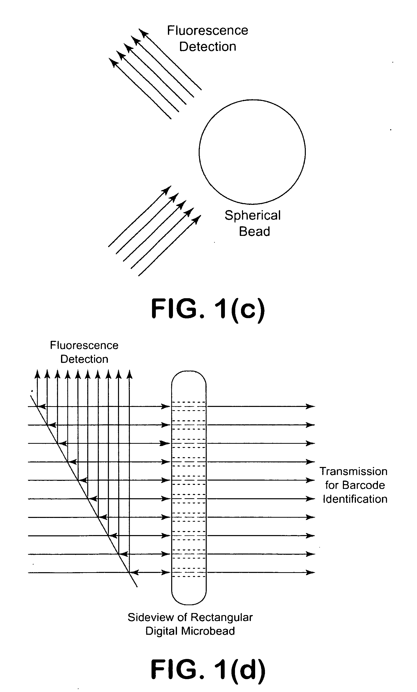
[0017]In another aspect of the present invention, the microfluidic chip with microchannel is designed to have configuration which can guide the rectangular bead, a non-spherical bead, in high speed flow with bead stability and no clogging. The microfluidic flow system has a pressure controlled device which can deliver the hydrodynamic flow to provide a rectangular bead with correct orientation and position in the flow system for accurate optical decoding and fluorescence detection.
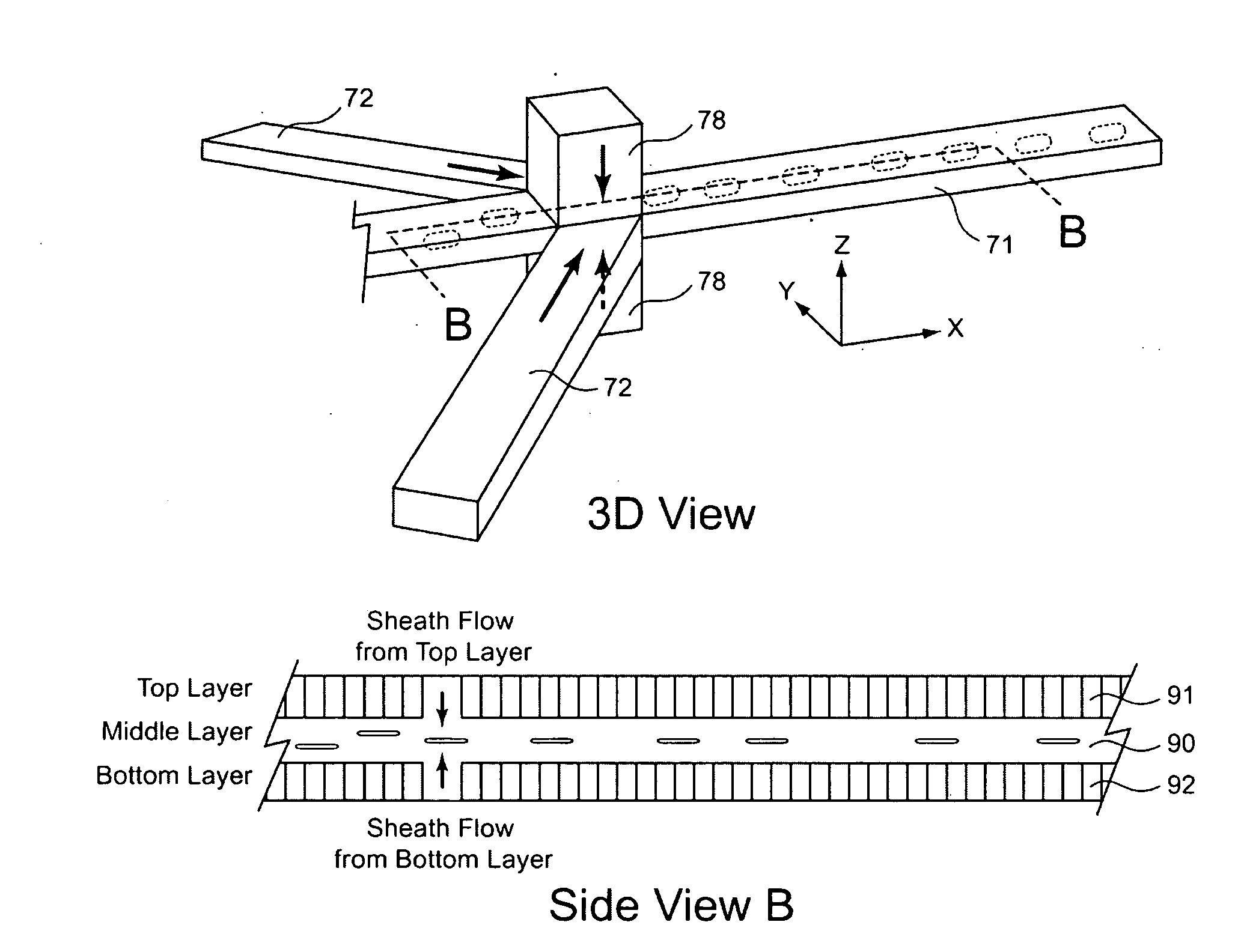
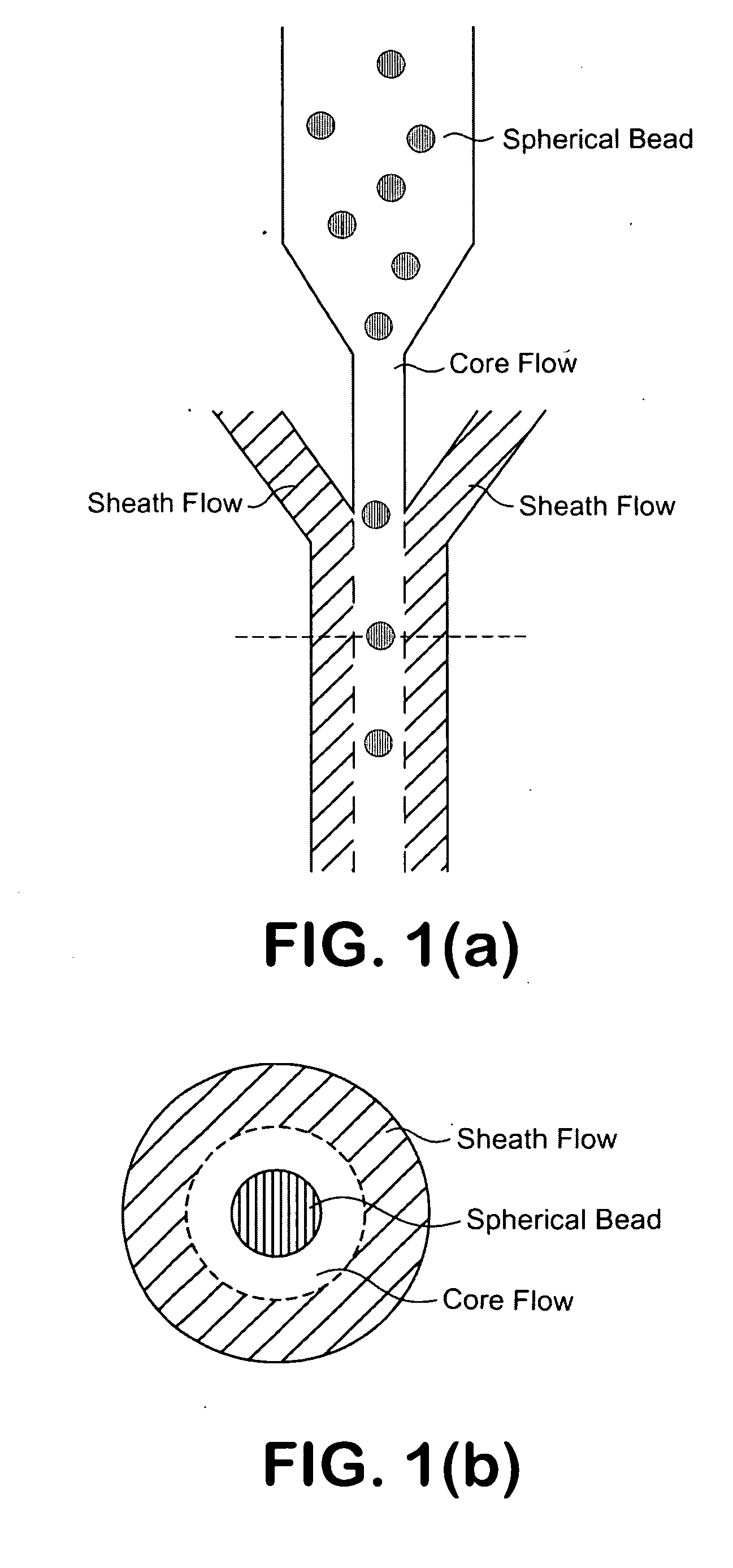
[0018]In another aspect of the present invention, a microfluidic apparatus comprises a one-dimensional or two-dimensional hydrodynamic flow system to control stable and proper bead orientation through the optical detection area. The hydrodynamic system include one core flow, which carries the rectangular barcode beads, and sheath flows, on the sides of or about or around the outer periphery of the core flow, pull the core flow into a proper dimension. The sheath flows, at a significantly higher volume flow rate compared to the core flow (e.g., about twice the volume flow rate of the core flow), but at a lower flow speed due to the significantly larger total cross sectional area of the sheath flows compared that of the core flow, can be pushed or pulled by vacuum, gravity, or pressure. By this method, the coded bead will align themselves in line and flow reliably, without wobbling or flipping, in the core flow channel through the detection zone. By adjusting the relative flow rate of core flow and sheath flows, the coded beads flow reliably in the flow system, thus it can be decoded and detected by an optical system accurately.

Problems solved by technology

No known flow system can control the position and orientation of the rectangular bead in the flow system.

Method used


Image

  • Hydrodynamic focusing for analyzing rectangular microbeads
  • Hydrodynamic focusing for analyzing rectangular microbeads
  • Hydrodynamic focusing for analyzing rectangular microbeads

Examples


Embodiment Construction

[0036]For purposes of illustrating the principles of the present invention and not by limitation, the present invention is described herein below by reference to a micro bead that is in the shape of a pallet, and by reference to bioanalysis. However, it is understood that the present invention is equally applicable to micro beads of other overall geometries that are not symmetrical in all orientations, and which are applied for other applications requiring identification based on the identity of the beads, without departing from the scope and spirit of the present invention. To facilitate discussion below, the micro bead of the present invention is referred to as a LITAB, which stands for a light transmitted assay bead, as disclosed in assignee's earlier patent applications noted above.

[0037]Non-Spherical, Rectangular Barcode Beads

[0038]In one aspect of the present invention, a micro bead is digitally coded as represented by a two-dimensional image that provides for high contrast an...


PUM


Abstract

A microfluidic apparatus having a one-dimensional or two-dimensional hydrodynamic flow system to control stable and proper digitally coded bead orientation through the optical detection area of a bioanalysis system. The hydrodynamic system include one core flow, which carries the rectangular barcode beads, and sheath flows, on the sides of or about or around the outer periphery of the core flow, pull the core flow into a proper orientation. The sheath flows, at much higher flow speed but lower volume flow rate, can be pushed or pulled by vacuum, gravity, or pressure. By this method, the coded bead will align themselves in line and flow reliably, without wobbling or flipping, in the core flow channel through the detection zone. By adjusting the relative flow rate of core flow and sheath flows, the coded beads flow reliably in the flow system, thus it can be decoded and detected by an optical system accurately.

Description

[0001]This application is a continuation-in-part application of: (a) U.S. patent application Ser. No. 12 / 069,720 filed Feb. 11, 2008, which is a continuation-in-part of U.S. patent application Ser. No. 11 / 580,514 filed Oct. 13, 2006 (which is in turn a continuation-in-part of U.S. patent application Ser. No. 11 / 502,606 filed Aug. 9, 2006), and which claims the benefit of the priority of U.S. Provisional Patent Application No. 60 / 706,896 filed Aug. 9, 2005; (b) U.S. Provisional Patent Application No. 60 / 964,108 filed Aug. 8, 2007; and (c) U.S. Provisional Patent Application No. 61 / 124,472 filed Apr. 17, 2008. These applications are fully incorporated by reference, as if fully set forth herein. All other publications and U.S. patent applications disclosed herein below are also incorporated by reference, as if fully set forth herein.BACKGROUND OF THE INVENTION[0002]1. Field of the Invention[0003]The invention relates to carry out multiplexed bioassay with hundreds or thousands of digit...

Claims


Application Information

Patent Timeline
Patent Type & Authority Applications(United States)
IPC IPC(8): G01B11/27G01F1/00
CPCB01L3/502761B01L3/502776B01L2200/0663G01N2015/1413B01L2300/0874G01N21/645B01L2300/0816
Inventor HO, WINSTONCOLLINS, JOHNLOW, PETER
Owner MAXWELL SENSORS
Why Eureka
Try Eureka