Simplified truss assembly and lighting track interconnection

a technology of interconnection and trusses, applied in the direction of lighting support devices, coupling device connections, lighting applications, etc., can solve the problems of clumsiness, large overall structure, and flimsy tracks themselves

Inactive Publication Date: 2009-08-13
CALLEJA MICHAEL J
View PDF7 Cites 11 Cited by
  • Summary
  • Abstract
  • Description
  • Claims
  • Application Information

AI Technical Summary

Benefits of technology

[0010]An advantage of the present invention is that a truss system is provided that does not allow incorrect or misaligned assembly by an installer.
[0011]Another advantage of the present invention is that a method is provided for the interconnection of low voltage power between truss sections.
[0012]The above and still further objects, features, and advantages of the present invention will become apparent upon consideration of the following detailed description of specific embodiments thereof, especially when taken in conjunction with the accompanying drawings.

Problems solved by technology

The power tracks themselves are usually very flimsy and need to be supported by bolting them to walls, ceilings, or support rods.
Line voltage track systems are dangerous and require large raceways that make the overall structures relatively large and clumsy.

Method used


Image

  • Simplified truss assembly and lighting track interconnection
  • Simplified truss assembly and lighting track interconnection
  • Simplified truss assembly and lighting track interconnection

Examples


Embodiment Construction

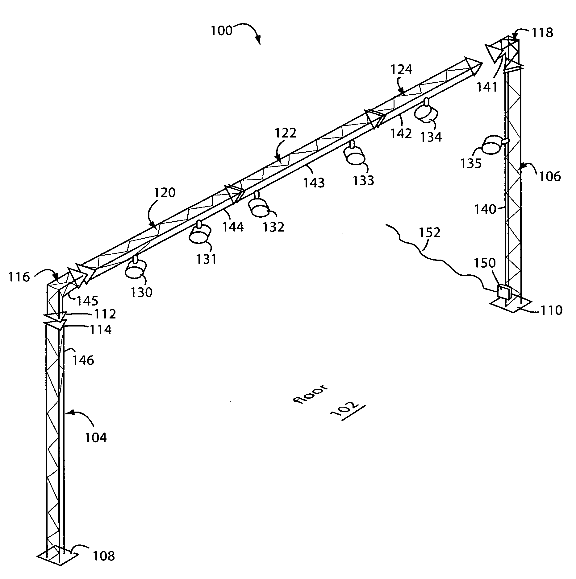
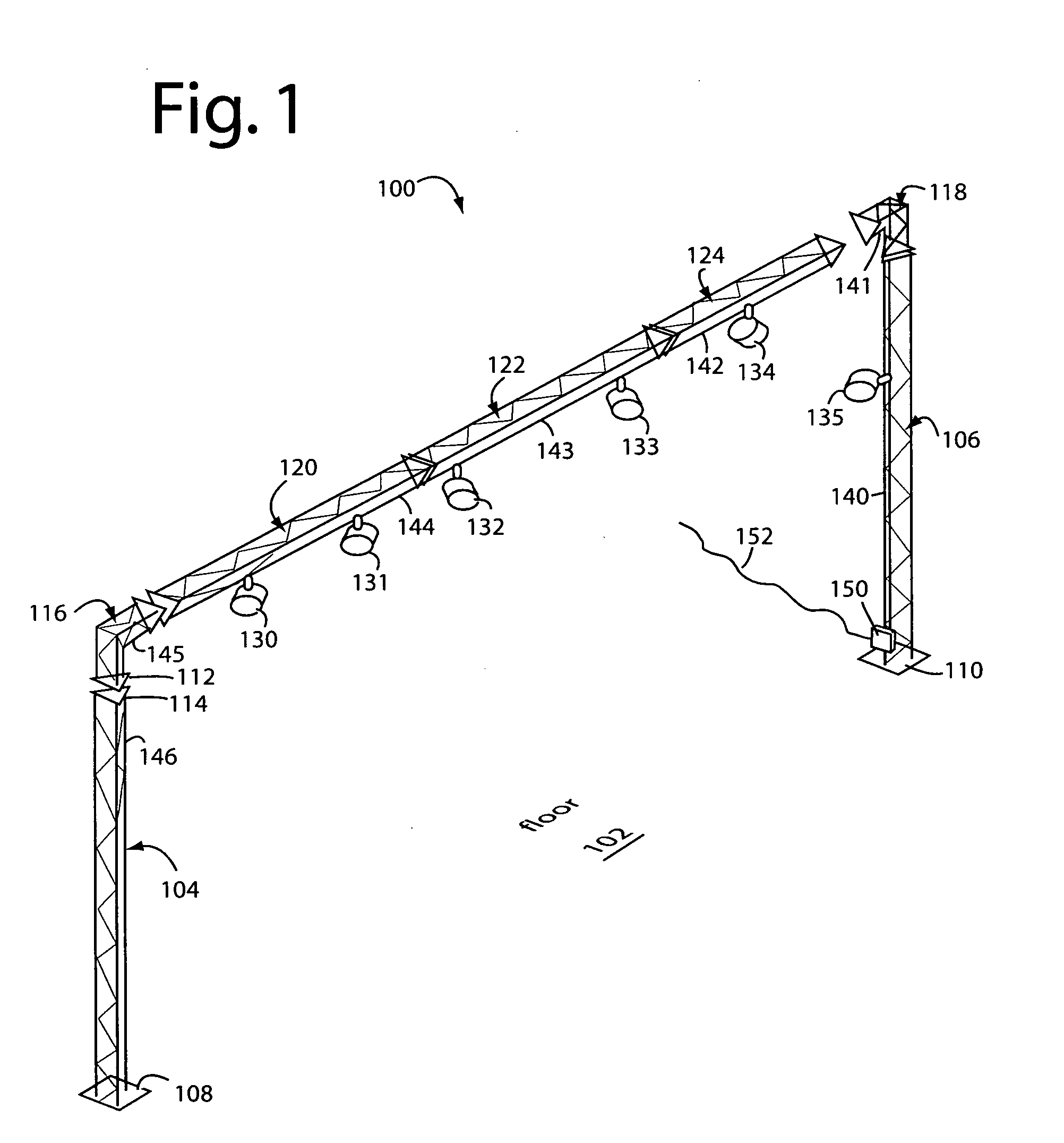
[0031]FIG. 1 represents a stage lighting truss system embodiment of the present invention, and is referred to herein by the general reference numeral 100. Truss system 100 may be arranged in many configurations suitable for the dimensions and uses of a floor 102. In one configuration, truss system 100 is made primarily from steel and comprises a pair of vertical supports 104 and 106 with base footings 108 and 110. A three-chord member, triangular construction is shown in FIG. 1, but 2-chord (I-beam), and 4-chord (square) truss pieces can also be used. A unique aspect is at least one of the chords has an electrical track and fixture slot within to accommodate and power low-voltage lighting heads.

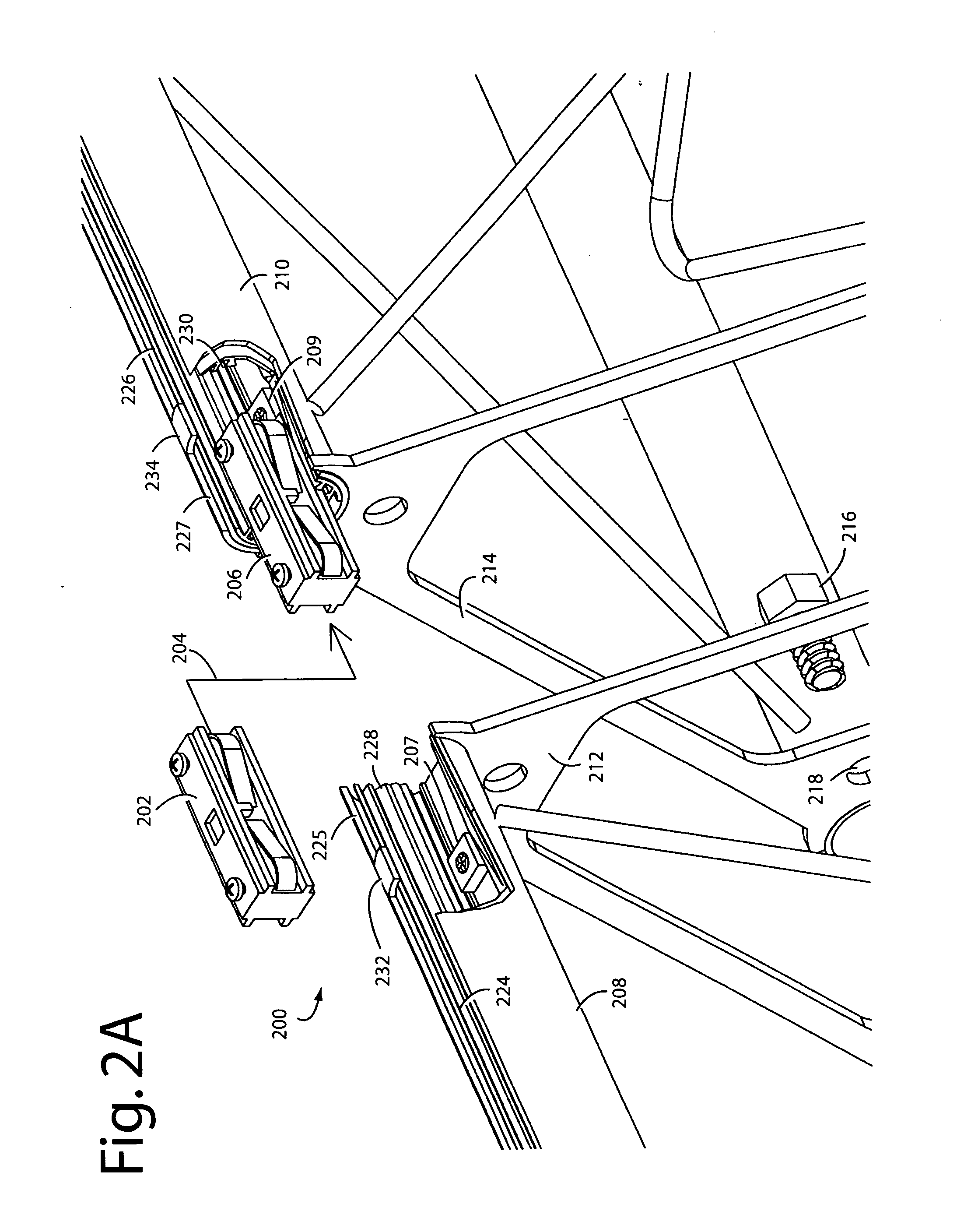
[0032]Each section is terminated with a welded triangular flange, e.g., 112 and 114. These bolt together and allow the modular assembly needed to custom configure each application of the system. An interconnector, shown in later Figs., allows daisy-chaining of the electrical power from one po...


PUM


Abstract

A simplified assembly truss system rivets each power track inside one chord of each truss span so that the electrical components cannot be misaligned inside the chord during final assembly. The chord is slotted to receive lighting heads in its mid-sections, and short end slots allow interconnecting plugs to be inserted into matching power track ends. A stop captured by the rivets near each chord-end indexes the interconnecting plugs to ensure the final electrical assembly is correct.

Description

RELATED APPLICATIONS[0001]This Application claims benefit of, and is a continuation-in-part of, U.S. patent application Ser. No. 12 / 069,201, filed Feb. 29, 2008, titled, TRUSS WITH LIGHTING TRACK, and is incorporated herein by reference.BACKGROUND OF THE INVENTION[0002]1. Field of the Invention[0003]The present invention relates to lighting truss systems typically used in homes, offices, retail space, stages and trade shows. In particular, the present invention relates to trusses with electrical buss bars, insulator supports, and extruded aluminum carriers disposed in at least one steel truss chord and accessible for track light fixtures through slots.[0004]2. Description of Related Art[0005]Trusses are widely used to support overhead lighting units powered by electrical power cords dressed along the truss raceways. Truss systems for stages and tradeshow floors are available in I-beam, triangle, and square truss sections made from aluminum or steel. Steel trusses are strong enough t...

Claims


Application Information

Patent Timeline
Patent Type & Authority Applications(United States)
IPC IPC(8): F21S8/02F21V19/00F21V21/14
CPCF21S2/00H01R25/145F21W2131/406F21V21/35
Inventor CALLEJA, MICHAEL J.
Owner CALLEJA MICHAEL J
Why Eureka
Try Eureka