Catalytic converter and method for manufacture thereof

Inactive Publication Date: 2006-04-25
CALSONICKANSEI NORTH AMERICA
View PDF16 Cites 5 Cited by
  • Summary
  • Abstract
  • Description
  • Claims
  • Application Information

AI Technical Summary

Benefits of technology

[0013]Accordingly, it is an advantage of the present invention that a catalytic converter and method for manufacture thereof is provided.
[0014]It is another advantage of the present invention that a method of manufacture of a catalytic converter is provided that eliminates the need for rolled seams while maintaining a gas-tight join in the fabrication of a converter shell.
[0015]It is another advantage of the present invention that a method of manufacture of a catalytic converter is provided that in one embodiment utilizes an Nd:YAG laser to create gas-tight joins in a final assembly.
[0016]It is another advantage of the present invention that a method of manufacture of a catalytic converter is provided in which no butt-welds exists.
[0017]The above and other advantages of the present invention are carried out in one form by a method for the manufacture of a catalytic converter incorporating fabricating a shell for the catalytic converter, loading a catalytic substrate into the shell, assembling an endcone for the catalytic converter, and laser welding the endcone to the shell.
[0018]The above and other advantages of the present invention are carried out in another form by a catalytic converter made up of a shell, a ceramic catalytic substrate loaded into the shell, an endcone fit to the shell, and a bead formed by laser welding the endcone to the shell.

Problems solved by technology

If a converter leaks, then the noxious gasses the converter is intended to catalyze may pass directly into the atmosphere, thereby defeating the purpose of the converter.
A leaky converter may also pass air into the converter.
Therefore, the passage of much cooler air into the converter may cause fracturing and other damage to the ceramic substrate.
This damage may reduce the converter efficiency, and may ultimately lead to converter failure.
Both rolled seams and MIG welding pose problems during manufacture.
A disadvantage of a rolled seam is that the seam is necessarily thick.
This produces a discontinuity in the shell that inhibits the proper joining of other components.
Such butt welds are prone to minor defects of the weld (the bead).
From the point of view of gas tightness, however, these minor defects may produce leaks over time.
MIG welding, though common, may develop leaks and severely limit the overall life of a catalytic converter.
Laser welding has been attempted with mixed success.
While an effective welding technique, laser welding has resulted in poor quality control because of excessive penetration (i.e., piercing).
Piercing often results in seals that are not gas tight, or in weak gas-tight seals leading to early failure during operation.

Method used


Image

  • Catalytic converter and method for manufacture thereof
  • Catalytic converter and method for manufacture thereof
  • Catalytic converter and method for manufacture thereof

Examples


Embodiment Construction

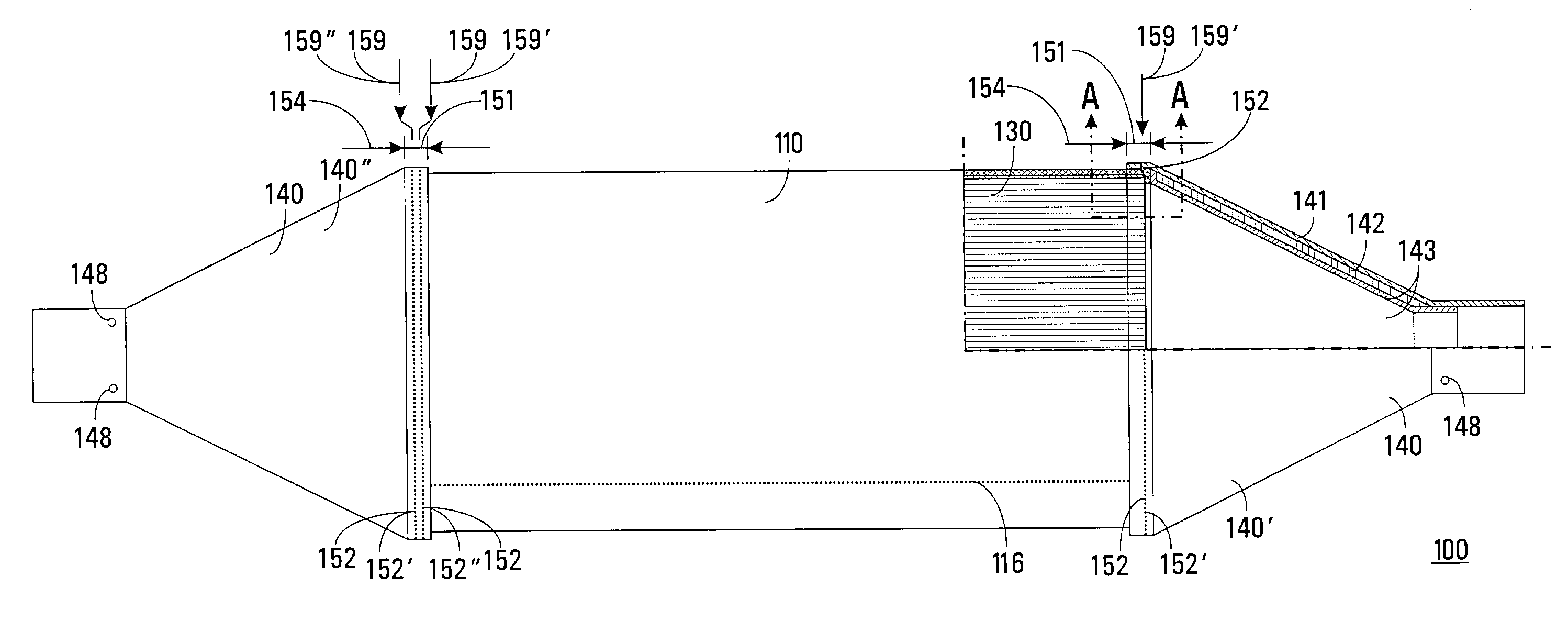
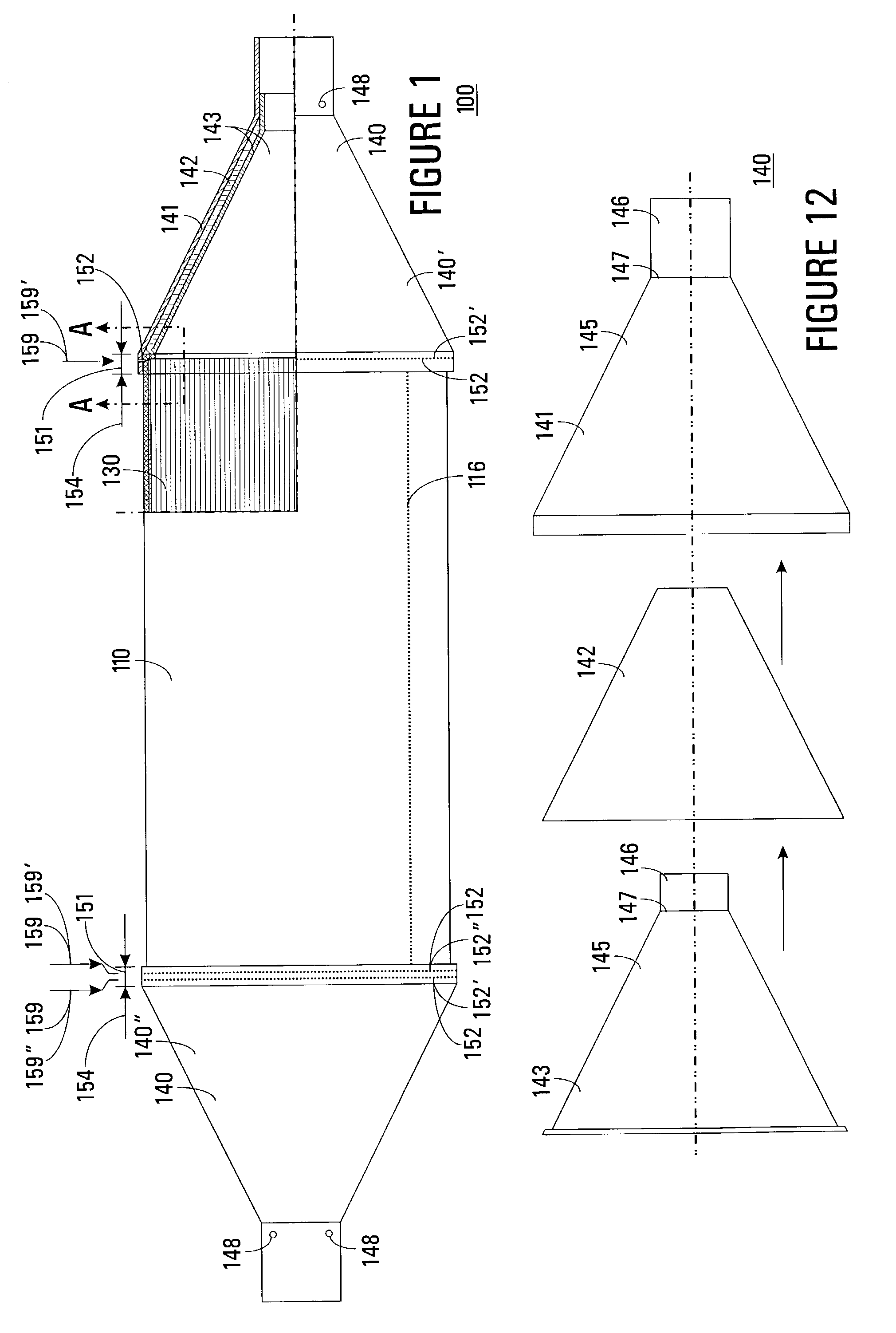
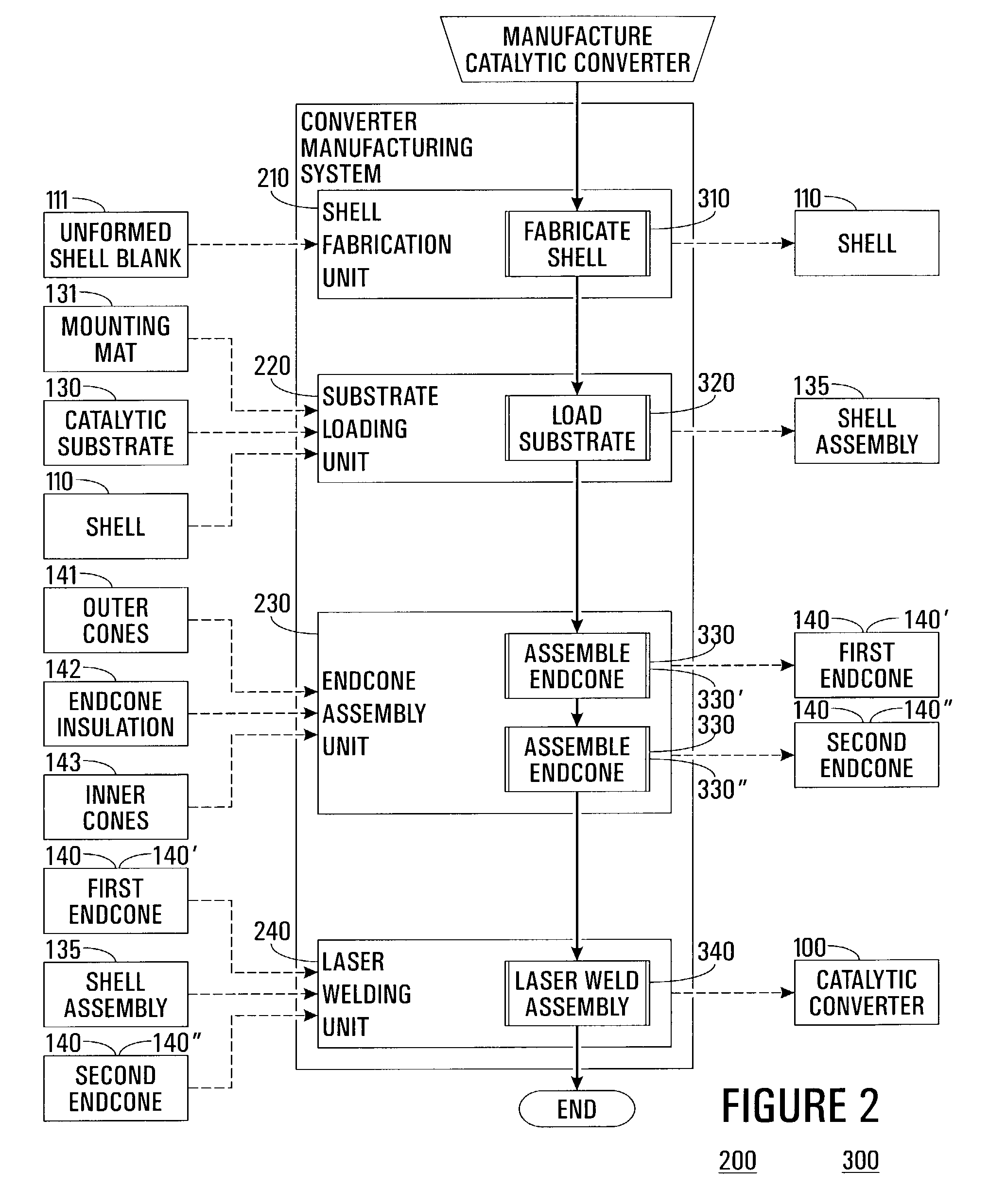
[0037]FIG. 1 shows a side view of a laser-welded cone-shell catalytic converter 100 with one corner cut away to depict internal components thereof. FIG. 2 shows a block diagram depicting a system 200 for the manufacture of catalytic converter 100, and a flowchart depicting a process 300 by which catalytic converter 100 may be manufactured by system 200 in accordance with a preferred embodiment of the present invention.

[0038]For purposes of clarity, a reference number assigned to an item identifies that same item throughout this discussion and in all relevant Figures. Catalytic converter 100 and all components thereof are assigned reference numbers between 100 and 199, inclusively. Similarly, catalytic-converter manufacturing system 200 and all components thereof are assigned reference numbers between 200 and 299, inclusively. Likewise, catalytic-converter manufacturing process 300 and all subprocesses and tasks thereof are assigned reference numbers between 300 and 399, inclusively....


PUM

PropertyMeasurementUnit
Lengthaaaaaaaaaa
Fractionaaaaaaaaaa
Fractionaaaaaaaaaa

Abstract

A system and method for the manufacture of a laser-welded cone-shell catalytic converter (100) is provided. An unformed shell blank (111) is formed into a cylindroid shell (110) having overlapping edges (112), which are then resistance welded to produce a shell seam (116). The shell seam (116) is planished to a thickness (120) less than 125 percent of a thickness (119) of the unformed shell blank (111). A ceramic catalytic substrate (130) is wrapped in a ceramic-fiber mounting mat (131) and inserted into the shell (110). Ends (125) of the shell (110) are crimped to form a 1 mm turndown (134). A pair of endcones (140) is assembled, where for each endcone (140) an outer cone (141) is loaded with an endcone insulation (142), and an inner cone (143) is pressed into and spot-welded to the outer cone (141). The endcones (140) are fitted to the shell (110) so as to form an overlap zone (151). The endcones (140) and shell (110) are then laser welded by an Nd:YAG laser (253) in the overlap zone (151).

Description

TECHNICAL FIELD OF THE INVENTION[0001]The present invention relates to the field of catalytic converters. More specifically, the present invention relates to the field of the manufacture of catalytic converters using laser welding.BACKGROUND OF THE INVENTION[0002]The automotive and light truck industries depend heavily upon catalytic converters to control exhaust emissions. These catalytic converters typically utilize ceramic substrates in the form of honeycombs coated with platinum and / or palladium to catalyze hydrocarbons, carbon monoxide, and nitrogen oxides in the exhaust into carbon dioxide, nitrogen, oxygen, and water.[0003]During manufacture, it is important that the catalytic converters be gas tight. That is, that the converters, when coupled into an exhaust system, do not leak. If a converter leaks, then the noxious gasses the converter is intended to catalyze may pass directly into the atmosphere, thereby defeating the purpose of the converter.[0004]A leaky converter may a...

Claims


Application Information

Patent Timeline
IPC IPC(8): B21D51/16B21D39/00B01D53/88B01D53/94B23K26/24B23K26/28B23P15/00F01N3/28F01N13/14F01N13/18
CPCB01D53/885B23K26/246B23K26/28B23P15/00F01N3/28F01N3/2853F01N13/14F01N13/1838B01D53/9454Y10T29/49345B23K2201/14B23P2700/03F01N2450/02F01N2450/22Y02T10/22Y10T29/49915B23K26/244B23K2101/14Y02T10/12
Inventor BURNETTE, STEPHEN L.STRUNK, LARRY E.
Owner CALSONICKANSEI NORTH AMERICA
Why Eureka
Try Eureka