Swirling flow producing apparatus, method of producing swirling flow, vapor phase generating apparatus, microbubble generating apparatus, fluid mixed and fluid injection nozzle

a technology of swirling flow and producing apparatus, which is applied in the direction of fluid heaters, light and heating apparatus, fluid mixing and packaging, etc., can solve the problems of low adaptability of each apparatus and the inability to increase the amount of treated fluid, so as to efficiently generate swirling flow and high-speed swirling flow , the effect of efficiently generating microbubbles

Inactive Publication Date: 2009-08-13
NAKATA COATING CO LTD
View PDF3 Cites 32 Cited by
  • Summary
  • Abstract
  • Description
  • Claims
  • Application Information

AI Technical Summary

Benefits of technology

[0017]That is, an object of the present invention is to provide a swirling flow producing apparatus that can be applied to any kind of fluid and can efficiently generate a swirling flow, and a method of producing swirling flow using the swirling flow producing apparatus. Further, another object of the present invention is to provide a vapor phase generating apparatus, a microbubble generating apparatus, a fluid mixer, and a fluid injection nozzle that use the apparatus.
[0053]Furthermore, according to the fluid injection nozzle of the present invention, as described above, the structures of the housing and the cylindrical member may be appropriately selected, combined with each other, and used. Therefore, while some components are shared, it is possible to freely control a ratio between the areas of an inlet and an outlet for the fluid; the angle, shape, and position of the hole; the number of the holes; and the surface roughness of each member, in accordance with the properties of the fluid to be injected. Further, the fluid injection nozzle can be applied to any kind of fluid. As a result, it is possible to efficiently inject any kind of fluid while swirling the fluid at high speed.

Problems solved by technology

However, there have been the following problems.
Further, the adaptability of each of the apparatuses is low.
Further, the apparatuses disclosed in these Patent Documents have problems in that the introduced liquid flows out only in one direction due to the structure of the apparatuses, a flowing-out direction is limited to one direction, and a large amount of treated fluid cannot be increased.

Method used


Image

  • Swirling flow producing apparatus, method of producing swirling flow, vapor phase generating apparatus, microbubble generating apparatus, fluid mixed and fluid injection nozzle
  • Swirling flow producing apparatus, method of producing swirling flow, vapor phase generating apparatus, microbubble generating apparatus, fluid mixed and fluid injection nozzle
  • Swirling flow producing apparatus, method of producing swirling flow, vapor phase generating apparatus, microbubble generating apparatus, fluid mixed and fluid injection nozzle

Examples


first embodiment

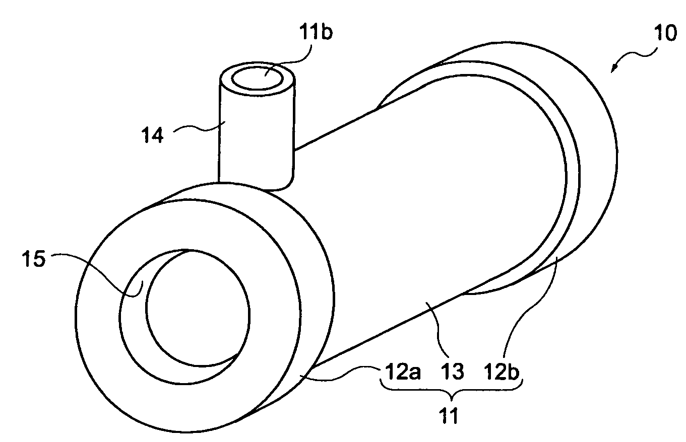
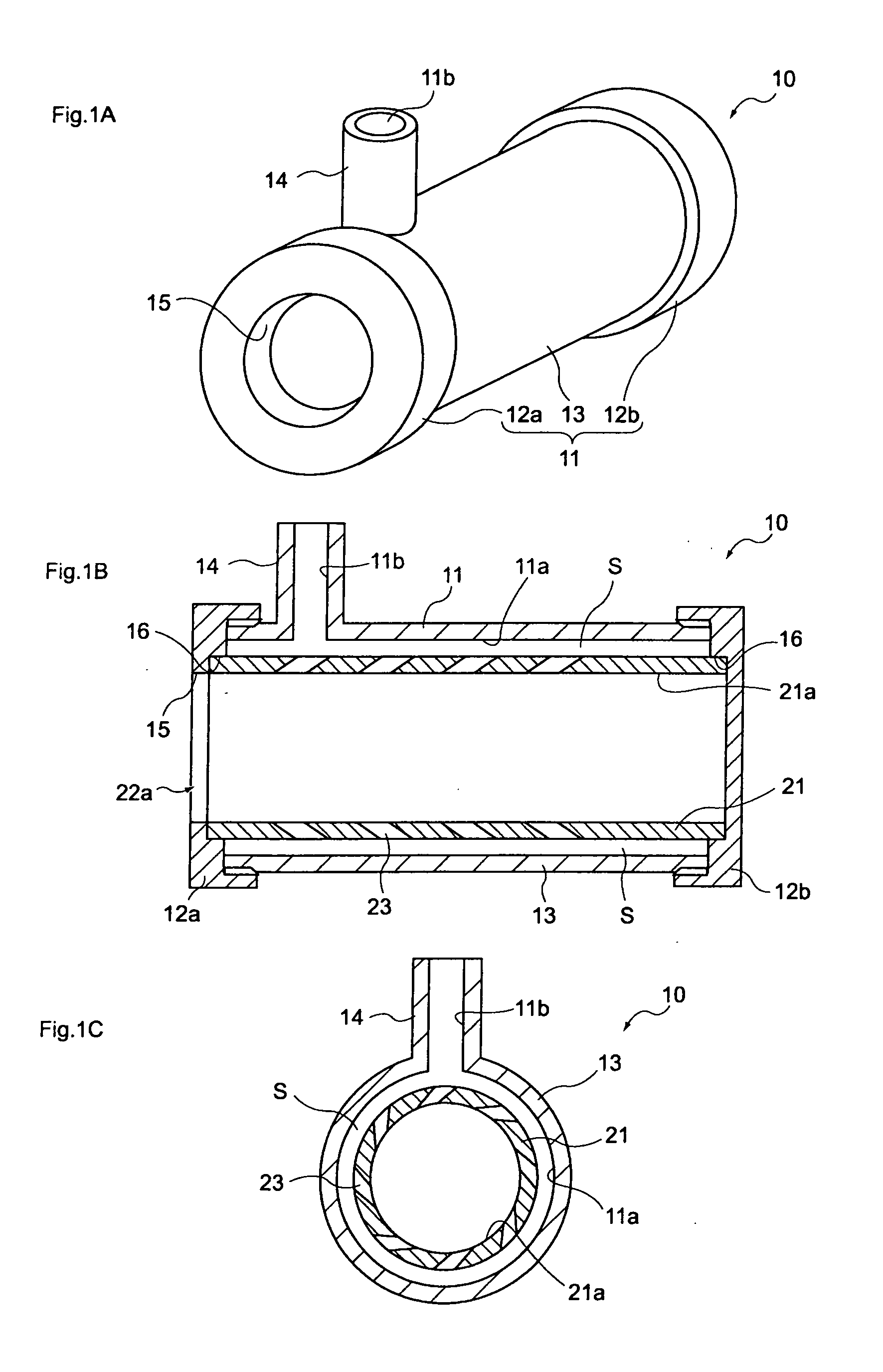
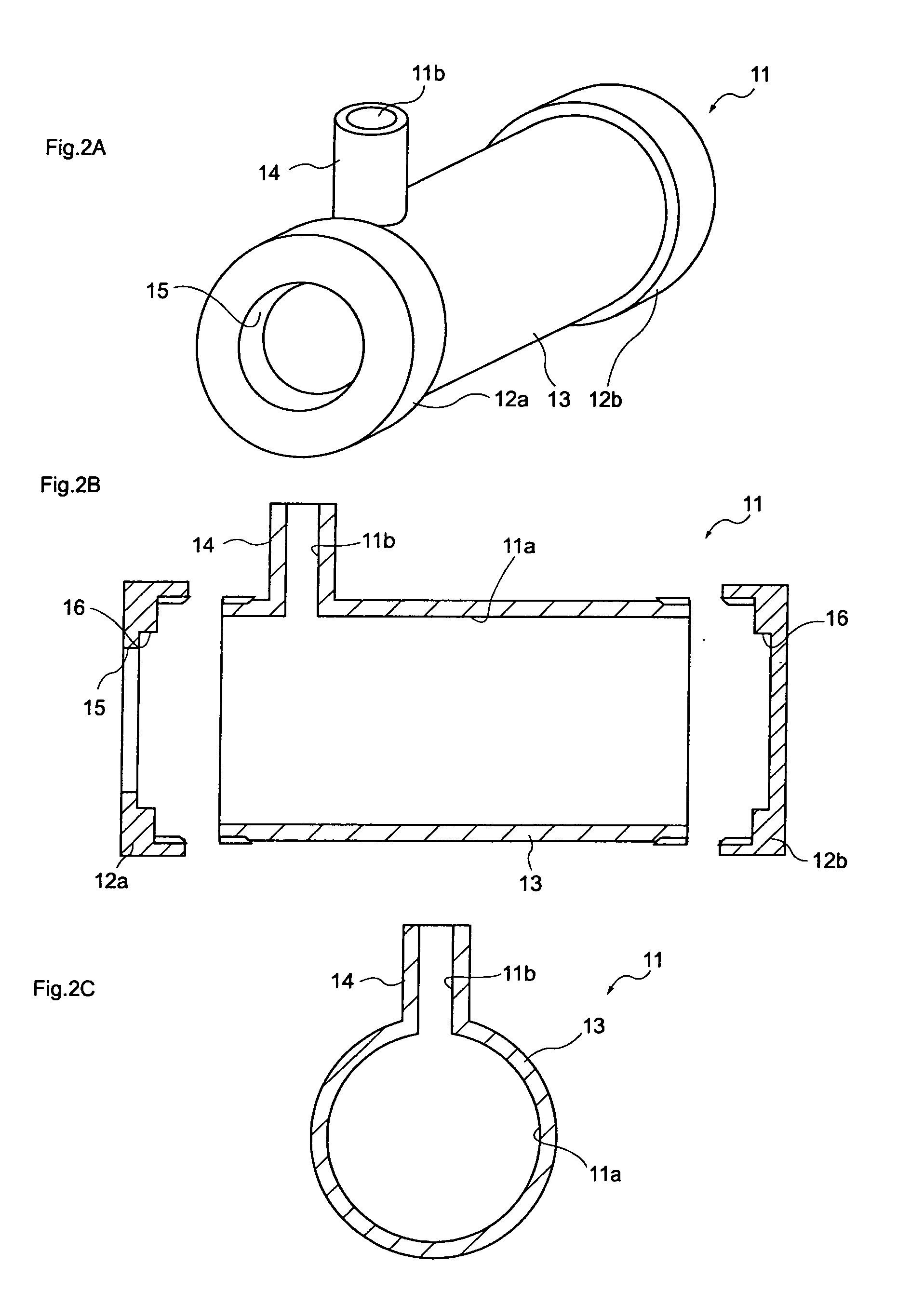
[0082]A first embodiment of the present invention provides a swirling flow producing apparatus and a method of producing swirling flow using the swirling flow producing apparatus. The swirling flow producing apparatus includes a housing and a cylindrical member. The housing includes a cylindrical portion of which at least one end is opened and a fluid introducing passage that is opened on an inner peripheral surface of the cylindrical portion. The cylindrical member is provided in the cylindrical portion of the housing. The cylindrical member includes a cylindrical portion of which at least one end in a direction corresponding to an opening direction of the cylindrical portion is opened, and holes formed at a peripheral wall of the cylindrical portion. A fluid introduced from the fluid introducing passage flows into the cylindrical portion of the cylindrical member through the holes so as to generate a swirling flow, and flows out from the housing and the cylindrical member.

1. Swirl...

second embodiment

[0135]A second embodiment of the present invention provides a vapor phase generating apparatus that uses the swirling flow producing apparatus described in the first embodiment. The vapor phase generating apparatus includes a housing and a cylindrical member. The housing includes a cylindrical portion of which at least one end is opened, and a fluid introducing passage that is opened on an inner peripheral surface of the cylindrical portion. The cylindrical member is provided in the cylindrical portion of the housing. The cylindrical member includes a cylindrical portion of which at least one end in a direction corresponding to an opening direction of the cylindrical portion is opened, and holes formed at a peripheral wall of the cylindrical portion. A fluid introduced from the fluid introducing passage flows into the cylindrical portion of the cylindrical member through the holes, and flows out from the housing and the cylindrical member while generating a swirling flow, so that a ...

third embodiment

[0139]A third embodiment of the present invention provides a microbubble generating apparatus that uses the swirling flow producing apparatus described in the first embodiment. The microbubble generating apparatus includes a housing and a cylindrical member. The housing includes a cylindrical portion of which at least one end is opened, and a fluid introducing passage that is opened on an inner peripheral surface of the cylindrical portion. The cylindrical member is provided in the cylindrical portion of the housing. The cylindrical member includes a cylindrical portion of which at least one end in a direction corresponding to an opening direction of the cylindrical portion is opened, and holes formed at a peripheral wall of the cylindrical portion. A fluid introduced from the fluid introducing passage flows into the cylindrical portion of the cylindrical member through the holes so as to generate a swirling flow, and flows out from the housing and the cylindrical member while gener...


PUM

PropertyMeasurementUnit
sizesaaaaaaaaaa
speedaaaaaaaaaa
pressure lossaaaaaaaaaa

Abstract

There are provided a fluid injection nozzle, a fluid mixer, a microbubble generating apparatus, a vapor phase generating apparatus, a method of producing swirling flow, and a swirling flow producing apparatus that can be applied to any kind of fluid and can efficiently generate a swirling flow at high speed.The swirling flow producing apparatus includes a housing and a cylindrical member. The housing includes a cylindrical portion of which at least one end is opened, and a fluid introducing passage that is opened on an inner peripheral surface of the cylindrical portion. The cylindrical member is provided in the cylindrical portion of the housing. The cylindrical member includes a cylindrical portion of which at least one end in a direction corresponding to an opening direction of the cylindrical portion is opened, and holes formed in a peripheral wall of the cylindrical portion. A fluid introduced from the fluid introducing passage flows into the cylindrical portion of the cylindrical member through the holes so as to generate a swirling flow, and flows out from the housing and the cylindrical member.

Description

BACKGROUND OF THE INVENTION[0001]1. Field of the Invention[0002]The present invention relates to a swirling flow producing apparatus, a method of producing swirling flow, a vapor phase generating apparatus, a microbubble generating apparatus, a fluid mixer, and a fluid injection nozzle. More particularly, the present invention relates to a swirling flow producing apparatus and a method of producing swirling flow that efficiently generate a high-speed swirling flow in a fluid, and a vapor phase generating apparatus, a microbubble generating apparatus, a fluid mixer, and a fluid injection nozzle that use the swirling flow producing apparatus.[0003]2. Description of the Related Art[0004]In the past, a technique for generating a swirling flow in liquid has been applied in various technical fields.[0005]For example, there has been a separation apparatus that can easily generate a stable swirling flow, can improve the separation efficiency of a mixed fluid while suppressing the pressure l...

Claims


Application Information

Patent Timeline
Patent Type & Authority Applications(United States)
IPC IPC(8): F24H9/00
CPCB01F3/0446B01F5/0057B01F5/0256B01F5/0475B01F5/0614B01F2015/0221B01F2005/0621B01F2005/0632B01F2005/0636B01F2005/0637B01F2005/0017B01F23/232B01F2025/913B01F25/23B01F25/10B01F25/31425B01F25/3142B01F25/4317B01F25/4314B01F25/43195B01F25/431972B01F25/431971B01F35/715
Inventor MATSUNO, TAKEMINAKATA, AKIO
Owner NAKATA COATING CO LTD
Why Eureka
Try Eureka