Method and device to determine a position shift of a focal area

a technology of focal area and position shift, which is applied in the field of hyperthermia application, can solve the problems of not being able to avoid damage to healthy tissue by a treating physician, and achieve the effects of preventing the start-up preventing the particular operation of the hyperthermia applicator, and preventing damage to healthy tissu

Inactive Publication Date: 2009-08-13
SIEMENS HEALTHCARE GMBH
View PDF6 Cites 4 Cited by
  • Summary
  • Abstract
  • Description
  • Claims
  • Application Information

AI Technical Summary

Benefits of technology

[0014]The invention is based on the insight that the image data containing temperature information can nevertheless be used to detect a position change. For this purpose, a position shift of the focal area is determined by an image data comparison. In this image data comparison, second image data containing temperature information are compared with first image data containing temperature information, meaning that an image data set acquired at a later point in time is compared with an image data set acquired earlier. First image data containing temperature information are basically acquired from a body region of the patient immediately after an appropriate positioning of the patient and obtaining a reference data set. By means of such a reference data set it is possible to establish a shift of the focal area (for example as a result of a slight movement of the patient) automatically, and thus essentially without time delay, as well as without the necessity of an interaction of a user (for example a physician) using a deviation in the subsequently acquired image data. A high resolution of anatomical details is not required for this.
[0030]As previously described, it is particularly advantageous to design the image acquisition apparatus as an MRT apparatus since both the acquisition of the image data containing temperature information and the image acquisition (frequently designed to be high-resolution) to determine the focal area are possible by means of the MRT apparatus. For example, a relocation of the patient can thereby be avoided, which in particular is advantageous with regard to the avoidance of a position change of the patient between the different acquisitions.

Problems solved by technology

Given such an oversight, for example, it is not possible for a treating physician to avoid damage to healthy tissue by a corresponding reaction (for example by refraining from starting up the hyperthermia applicator).

Method used


Image

  • Method and device to determine a position shift of a focal area
  • Method and device to determine a position shift of a focal area

Examples


Embodiment Construction

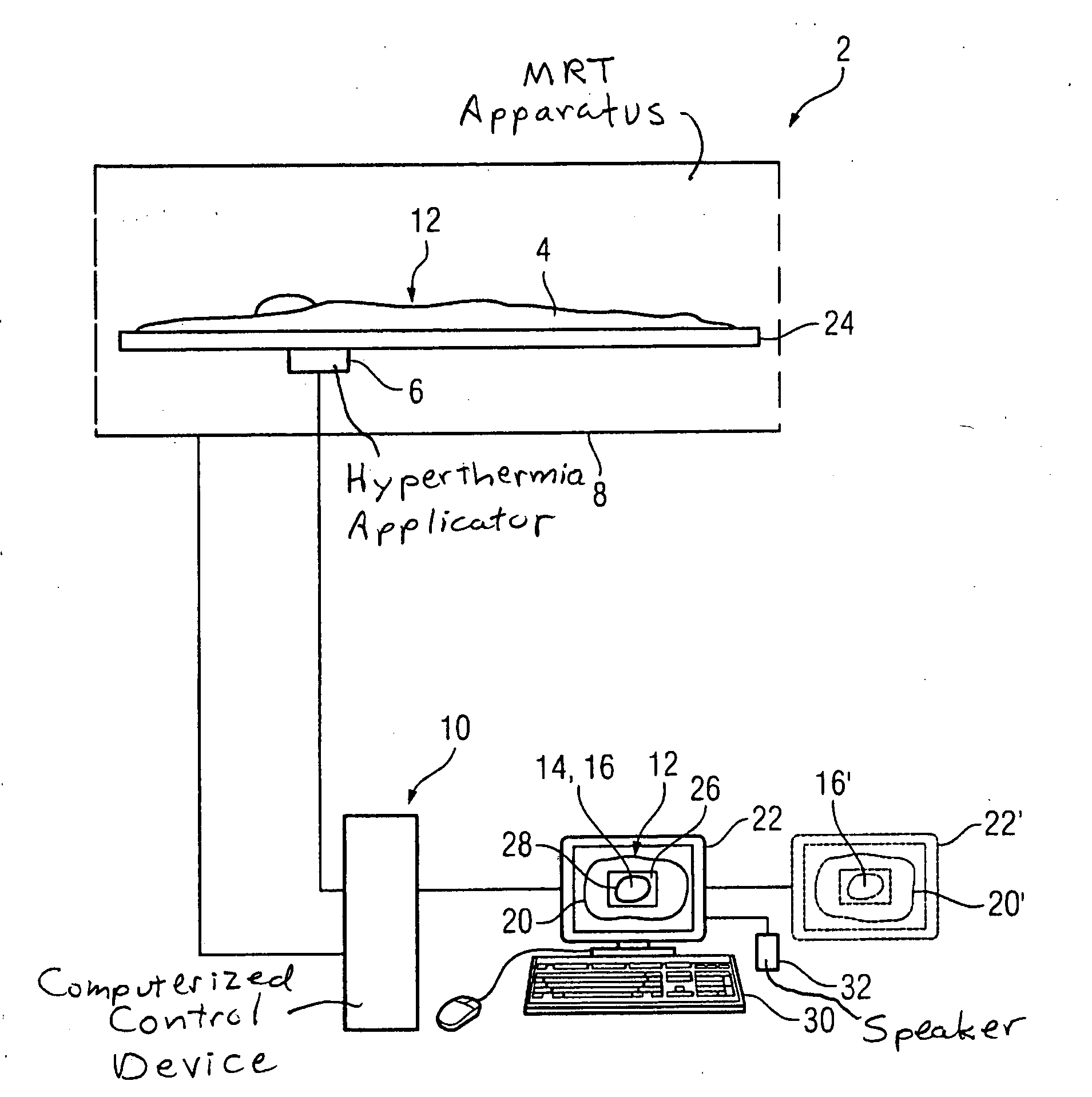
[0038]The FIGURE shows a device 2 to determine a position shift of a focal area. A hyperthermic treatment of a tumor tissue of a patient 4 can be implemented with the device 2.

[0039]In particular, a method workflow of an embodiment of the method according to the invention should be explained using the representation.

[0040]The presented device 2 has a hyperthermia applicator 6, an image acquisition apparatus executed as a magnetic resonance tomography apparatus 8 (MRT apparatus) and a computer as a control device 10.

[0041]High-resolution image exposures of a dorsal body region 12 of the real positioned patient 4 are initially acquired by means of the MRT apparatus 8. The corresponding image exposures are 2D image exposures which are acquired in a scan operation of the MRT apparatus 8. As an alternative, it is also possible to acquire high-resolution 3D image data of the body region 12. The 2D image exposures deliver a very detailed depiction of anatomical features of the body region ...


PUM


Abstract

In a method and device for determination of a position shift, first image data of a body region of a treatment-positioned patient that contain derivable temperature information are acquired. A focal area in the body region is determined, and the focus of a hyperthermia applicator can be aligned on the focal area. Second image data of the body region of the treatment-positioned patient that contain derivable temperature information are acquired, and a position shift of the focal area is determined by a comparison of the second image data with the first image data.

Description

BACKGROUND OF THE INVENTION[0001]1. Field of the Invention[0002]The present invention concerns a method to determine a position shift of a focal area as well as a corresponding device. The invention in particular concerns such a method and device in the field of hyperthermia application.[0003]2. Description of the Prior Art[0004]Hyperthermic treatment of tumor tissue has attracted increasing interest in medical cancer treatment. In such a hyperthermic treatment of tumor tissue (also called hyperthermia) the tumor tissue is heated to temperatures of over 42.5° C. Hyperthermia in cancer treatment is frequently used as a measure supporting radiation and / or chemotherapy. Hyperthermic treatment of tumor cells in which these cells are heated to temperatures of, for example, above 60° C., is often referred to as heat therapy; such treatment generally leads to a heat-induced destruction of the tumor cells.[0005]In hyperthermia, differentiation is made between whole-body hyperthermia and loc...

Claims


Application Information

Patent Timeline
Patent Type & Authority Applications(United States)
IPC IPC(8): A61B5/05
CPCA61B5/015A61B5/055A61B18/18A61B18/20A61B2019/5265A61N1/403G01R33/56509A61N7/02G01R33/4804G01R33/4808G01R33/4814G01R33/5608A61N5/04A61B2034/2065
Inventor STEINMEYER, FLORIANZWANGER, MICHAEL
Owner SIEMENS HEALTHCARE GMBH
Why Eureka
Try Eureka