Safety locking device for a lifting hook

a safety locking and lifting hook technology, applied in the field of safety locking devices for lifting hooks, can solve the problems of complicated manufacturing and installation of safety locking devices at lifting hooks, and achieve the effect of easy manufacturing and installation

Inactive Publication Date: 2009-08-20
LIKO RES & DEV
View PDF5 Cites 5 Cited by
  • Summary
  • Abstract
  • Description
  • Claims
  • Application Information

AI Technical Summary

Benefits of technology

[0003]The object of the invention is to achieve a safety locking device for a lifting hook, which device is easy to manufacture, install and comprises only one component part.
[0004]Said object is achieved according to the invention in that the safety locking device for a lifting hook comprises a lifting part and a hook part having a first and a second shank arranged in the same plane, the first shank being joined to the lifting part, the safety locking device being pivotably attached to either of the shanks or the lifting part and comprises a spring means formed integrally with the safety locking device to automatically bring the safety locking device to bear against the lifting part or the opposite shank for preventing unhooking of a hoisting cable or similar means introduced into the hook part, said safety locking device having a general U-shape with two legs, characterized in that the spring means is elongated and fixed at one of its ends to that part of the U-shaped safety locking device which connects the two legs of the U, and that the other part of the spring means is arranged to bear on either of the shanks or the lifting part of the lifting hook.

Problems solved by technology

The safety locking device is thereby complicated to manufacture and install at the lifting hook.

Method used


Image

  • Safety locking device for a lifting hook
  • Safety locking device for a lifting hook
  • Safety locking device for a lifting hook

Examples


Embodiment Construction

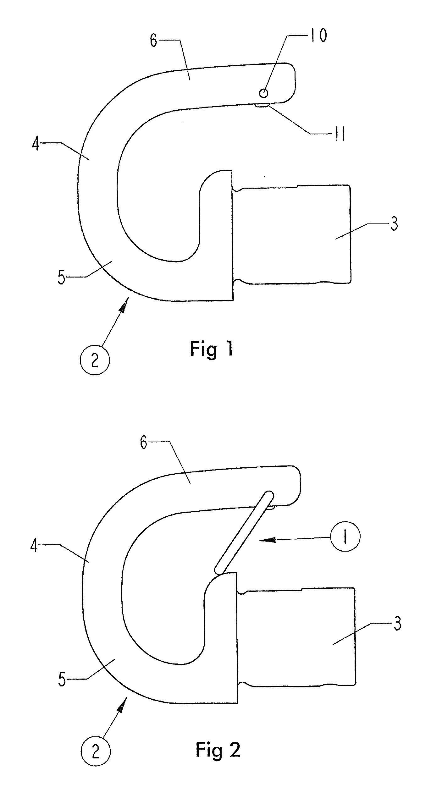
[0011]FIG. 1 shows a lifting hook 2 without a safety locking device 1 according to the invention. In this figure the preferred location of a hole 10 for pivotable supporting of the safety locking device 1 is shown, which hole 10 will be described below. A protrusion 11 is arranged on the side of a shank 6 facing a lifting part 3 of the lifting hook 2.

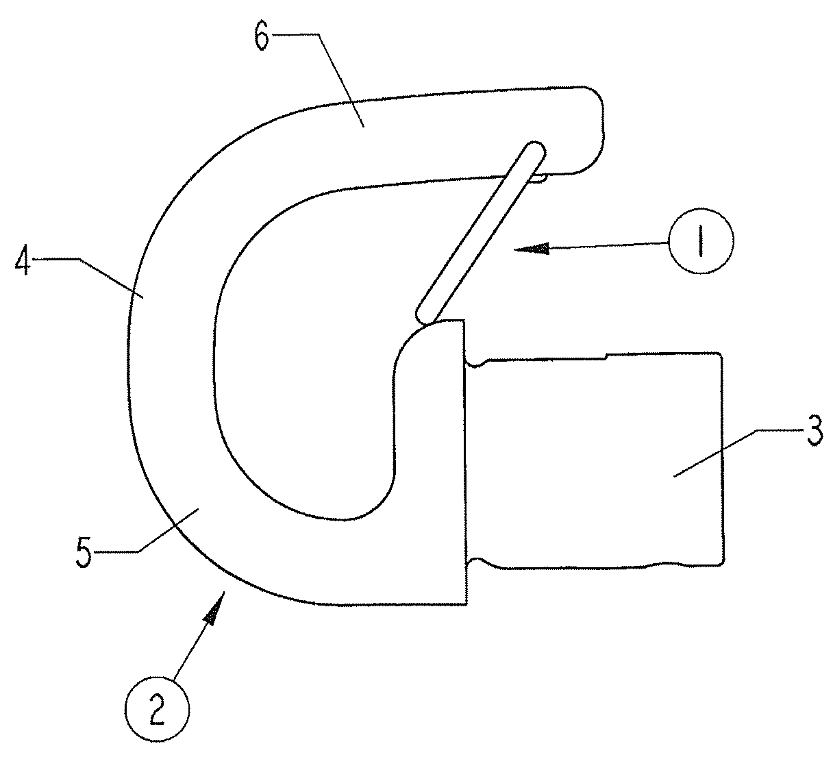
[0012]FIG. 2 shows the safety locking device 1 for the lifting hook 2, preferably a lifting hook intended for lifting patients within medical services, and comprises a lifting part 3 and a hook part 4, which comprises a first and a second shank 5, 6, the first shank 5 being connected to the lifting part 3, and the second shank 6 extends beyond at least a portion of the lifting part 3, i.e. the second shank 6 is longer than the first shank 5. Preferably the first shank 5 is formed integrally with the lifting part 3. The safety locking device 1 is pivotably attached to one of the shanks 5, 6 of the lifting hook 2 or the lifting part 3.

[00...


PUM


Abstract

A safety locking device (1) for a lifting hook (2) comprising a lifting part (3) and a hook part (4) having a first and a second shank (5, 6) arranged in the same plane, the first shank (5) being attached to the lifting part (3). The safety-locking device (1) is pivotably attached to either of the shanks or the lifting part (3) and comprises a spring means (7) formed integrally with the safety locking device, one end of which is attached to the safety locking device (1) diametrically opposed its fastening point to either shank or the lifting part and the other end is arranged to bear on the opposite shank or the lifting part (3), to which the safety locking device is pivotably attached to automatically bring the safety locking device (1) to bear on the lifting part (3) or the opposite shank so as to prevent unhooking of a hoisting cable or similar means introduced into the hook part.

Description

FIELD OF THE INVENTION[0001]The present invention relates to a safety locking device for a lifting hook according to the preamble of claim 1.BACKGROUND OF THE INVENTION[0002]It is known to provide lifting hooks with safety locking devices. However, these safety locking devices comprise several parts, such as locking means and locking springs, for instance, to close the safety locking device against the lifting hook itself. The safety locking device is thereby complicated to manufacture and install at the lifting hook.SUMMARY OF THE INVENTION[0003]The object of the invention is to achieve a safety locking device for a lifting hook, which device is easy to manufacture, install and comprises only one component part.[0004]Said object is achieved according to the invention in that the safety locking device for a lifting hook comprises a lifting part and a hook part having a first and a second shank arranged in the same plane, the first shank being joined to the lifting part, the safety l...

Claims


Application Information

Patent Timeline
Patent Type & Authority Applications(United States)
IPC IPC(8): B66C1/36
CPCA61G7/1078F16B45/02B66C1/36F16B45/036
Inventor LILJEDAHL, GUNNAR
Owner LIKO RES & DEV
Why Eureka
Try Eureka