Method and device for the production of a plastic profile

a technology of plastic profiles and curved profiles, applied in the direction of dough shaping, lamination, printing, etc., can solve the problems of not being able to flexibly flexibly, subjected to tensile stress,

Active Publication Date: 2009-08-20
3B LUX SARL
View PDF2 Cites 24 Cited by
  • Summary
  • Abstract
  • Description
  • Claims
  • Application Information

AI Technical Summary

Benefits of technology

[0018]According to a development of the apparatus, it is envisaged to provide the holding means with a releasable gripping or clamping mechanism for the finished plastic profile. The releasable gripping or clamping mechanism can securely hold the plastic profile when the die is intended to move in relation to the same; however, by releasing the gripping or clamping mechanism, the respective holding means can also be moved in relation to the plastic profile. In this way, step-by-step moving back of the holding means with respect to the plastic profile is also possible. As a result, after the moving back of the die counter to the direction of production of the plastic profile, while the or each holding means with the plastic profile held by it is stationary, the respective holding means can be moved back in front of the die. In this way, both the holding means and the die can perform step-by-step movements, to be precise both together and independently of each other, that is separately.
[0019]A further form of the apparatus envisages arranging at least the die, preferably also the respective holding means or all the holding means, on a carriage of its own in each case. In this way, the die and the holding means can be moved back and forth independently of one another step by step along the plastic profile. The different carriages for the die and the holding means or all the holding means are arranged in succession, seen in the direction of production, in the vicinity of the plastic profile, the carriage for the respective holding me

Problems solved by technology

The further moving of the die in relation to the plastic profile has the effect that a portion of the completed and cured plastic profile emerges from the die without the previo

Method used


Image

  • Method and device for the production of a plastic profile
  • Method and device for the production of a plastic profile
  • Method and device for the production of a plastic profile

Examples


Embodiment Construction

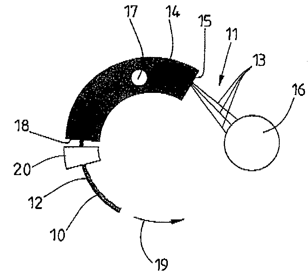
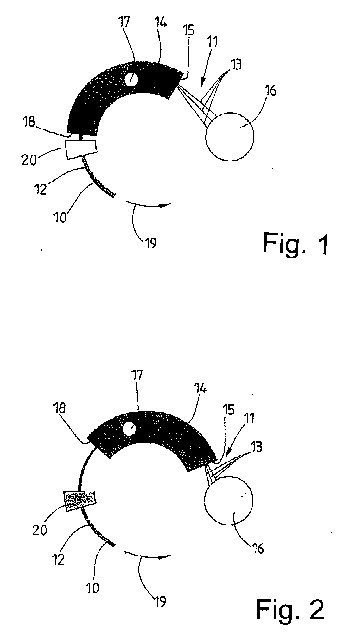
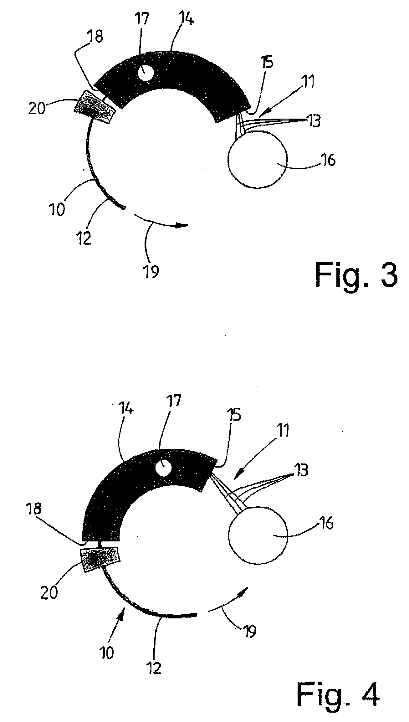
[0035]The figures schematically show an apparatus according to the invention, which also serves for carrying out the process according to the invention. This apparatus is a pultrusion apparatus for a plastic profile 10 with an internal reinforcement 11 and a plastic 12, preferably a thermoset, surrounding the latter. In the exemplary embodiment, which is only shown schematically, it is assumed that the reinforcement 11 comprises three endless strands 13 of preferably high-tensile fibers, for example carbon fibers. However, any other desired reinforcements, for example of woven and / or knitted fabrics or a combination of the strands 13 with woven and / or knitted fabrics, may also be embedded in the plastic 12 of the plastic profile 10. The invention is also not restricted to the three strands 13 that are shown in the figures.

[0036]With the schematically shown apparatus and the process according to the invention, plastic profiles 10 of any desired shape can be produced by pultrusion. Sh...


PUM

PropertyMeasurementUnit
Shapeaaaaaaaaaa
Distanceaaaaaaaaaa
Elasticityaaaaaaaaaa

Abstract

In the production of elongate plastic profiles (10), which usually takes place by the pultrusion process, the cured plastic profile (10) emerging from a die (14) is pulled through the stationary die (14) by a take-off device. This process only makes it possible to produce straight plastic profiles (10). The invention envisages producing curved plastic profiles (10) by using a die (14) corresponding to the curvature of the plastic profile (10). For moving the cured part of the plastic profile (10) out of the die (14), it is provided that the die (14) is moved back step by step in relation to the stationary plastic profile (10) counter to the direction of production (19). In order that the plastic profile (10) remains stationary in relation to the die (14) as this takes place, it is securely held outside the die (14) by a holding means (20) during the moving back of the die (14).

Description

STATEMENT OF RELATED APPLICATIONS[0001]This application is the U.S. National phase Under Chapter II of the Patent Cooperation Treaty (PCT) of PCT International Application No. PCT / EP2008 / 001954 having a filing date of 12 Mar. 2008, which claims priority on German Patent Application No. 10 2007 014 578.2 having a filing date of 23 Mar. 2007.BACKGROUND OF THE INVENTION[0002]1. Technical Field[0003]The invention relates to a process for producing a plastic profile, a continuous reinforcement comprising strands, woven fabrics and / or the like being led through a die and embedded in the plastic in the die, and to an apparatus for producing a plastic profile, comprising a die, in which a continuous reinforcement of the plastic profile can be embedded in liquid plastic.[0004]2. Related Art[0005]Straight plastic profiles comprising plastic and a continuous reinforcement of fibers, woven and / or knitted fabrics, which are embedded in the plastic, are mostly produced continuously in a strand. T...

Claims


Application Information

Patent Timeline
IPC IPC(8): B29C70/28B29C47/34B29C48/355
CPCB29C70/56B29C70/525
Inventor JANSEN, KLAUSWEIDLER, DIETMARHOFFMANN, MARIAN
Owner 3B LUX SARL
Why Eureka
Try Eureka