Display device

a technology of a display device and a counter substrate, which is applied in the direction of instruments, non-linear optics, optics, etc., can solve the problems of liquid crystal material leakage, adhesion failure between the sealing material and the counter substrate (or the tft substrate),

Active Publication Date: 2009-08-20
PANASONIC LIQUID CRYSTAL DISPLAY CO LTD +1
View PDF6 Cites 21 Cited by
  • Summary
  • Abstract
  • Description
  • Claims
  • Application Information

AI Technical Summary

Benefits of technology

[0027]According to the display device of the present invention, even when the distance L2 of the second columnar members and the distance of the third columnar members are smaller than predetermined values, for example, the third columnar members function a

Problems solved by technology

Still further, in manufacturing the TFT-type liquid crystal display panel, when the liquid crystal material is hermetically filled by a liquid-crystal dropping filling method (ODF method) and a dropping quantity of th

Method used


Image

  • Display device
  • Display device
  • Display device

Examples


Embodiment Construction

[0037]Hereinafter, embodiments of the present invention are explained in detail in conjunction with attached drawings.

[0038]Here, in all drawings for explaining the embodiments, parts having identical functions are given same symbols and their repeated explanation is omitted.

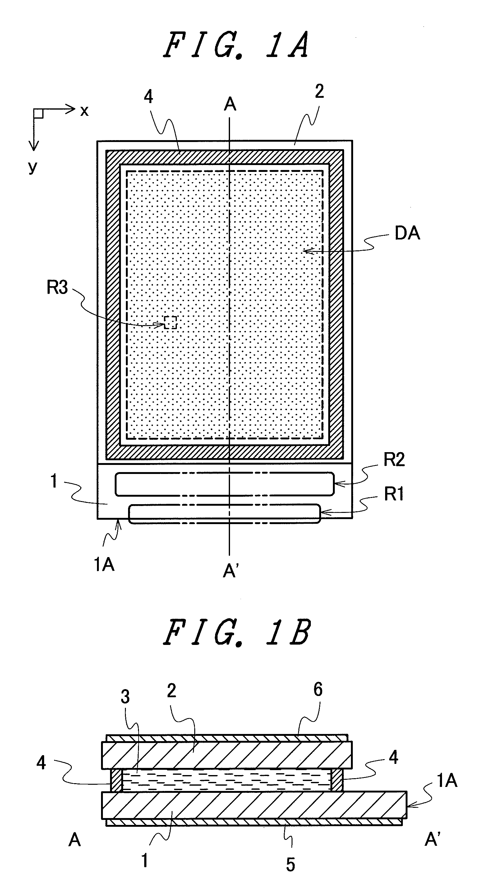
[0039]FIG. 1A to FIG. 1C are schematic views showing one example of the schematic constitution of a conventional liquid crystal display panel.

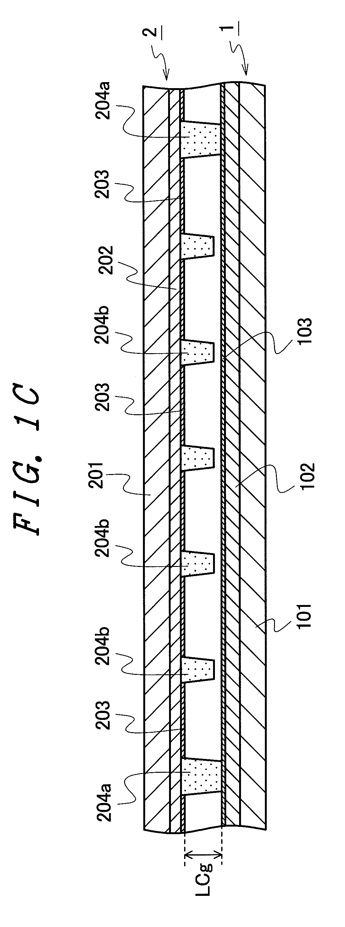
[0040]FIG. 1A is a schematic front view showing one example of the schematic constitution of the conventional liquid crystal display panel. FIG. 1B is a schematic cross-sectional view showing one example of the cross-sectional constitution taken along a line A-A′ in FIG. 1A. FIG. 1C is a schematic cross-sectional view showing one example of the schematic constitution of a TFT substrate and a counter substrate within a display region DA in FIG. 1A.

[0041]Here, the cross-sectional constitution shown in FIG. 1C is not the cross-sectional constitution taken along a specific str...


PUM


Abstract

The generation of bubbles in a liquid crystal material of a liquid crystal display panel and the generation of color irregularities when the liquid crystal display panel is pushed can be reduced. In a display device having a liquid crystal display panel in which a liquid crystal material is filled between a first substrate and a second substrate, the second substrate forms, on a surface of an insulation substrate which faces the first substrate, first columnar members, second columnar members and third columnar members which differ from each other in a distance from the surface of the insulation substrate to a top portion of each columnar member. Assuming the distance of the first columnar member as L1, the distance of the second columnar member as L2 and the distance of the third columnar member as L3, a relationship among the distances L1, L3, L2 satisfies L1>L3>L2, and assuming the number of the first columnar members arranged on the surface of the insulation substrate as N1, the number of the second columnar members arranged on the surface of the insulation substrate as N2 and the number of the third columnar members arranged on the surface of the insulation substrate as N3, a relationship among the numbers N1, N2, N3 satisfies N2>N1>N3.

Description

CLAIM OF PRIORITY[0001]The present application claims priority from Japanese application serial No. 2008-32564, filed on Feb. 14, 2008, the content of which is hereby incorporated by reference into this application.BACKGROUND OF THE INVENTION[0002]1. Field of the Invention[0003]The present invention relates to a display device, and more particularly to a technique which is effectively applicable to a liquid crystal display device manufactured by a liquid-crystal dropping filling method.[0004]2. Description of the Related Art[0005]Conventionally, the TFT-type liquid crystal display device has been used as a display of portable electronic equipment such as a mobile phone terminal, an external display of a television receiver set or a personal computer (PC) and the like.[0006]The TFT-type liquid crystal display device is a display device which includes a TFT-type liquid crystal display panel in which a liquid crystal material is filled between a pair of substrates. Here, the pair of su...

Claims


Application Information

Patent Timeline
IPC IPC(8): G02F1/1339
CPCG02F2001/13396G02F1/13394G02F1/13396
Inventor YAMAMOTO, TAKASHIARAI, YOSHIHIROTSUCHIYA, AKIKIKUCHI, NAOKI
Owner PANASONIC LIQUID CRYSTAL DISPLAY CO LTD
Why Eureka
Try Eureka