Tapered roller bearing apparatus

a technology of tapered roller bearings and roller bearings, which is applied in mechanical equipment, differential gearings, gearings, etc., can solve the problems of affecting the operation of the gearing, the lubricating oil cannot be expected to be supplied thereto, and etc., and achieves the effect of suppressing the seizure of the gearing

Inactive Publication Date: 2009-08-20
JTEKT CORP
View PDF4 Cites 15 Cited by
  • Summary
  • Abstract
  • Description
  • Claims
  • Application Information

AI Technical Summary

Benefits of technology

[0007]The invention is accomplished in view of such circumstances. Accordingly, an object of the invention is to provide a tapered roller bearing apparatus for a pinion shaft of a differential device, which can maintain an appropriate lubrication state and suppress occurrence of seizure of a tapered roller bearing apparatus.
[0016]Consequently, even when the oil level of the lubricating oil stored in the housing is inclined, an appropriate lubricating state can be maintained. In addition, seizure can be suppressed from occurring in the tapered roller bearing.
[0018]In this case, the annular wall portion can prevent all the lubricating oil in the bearing from flowing out of the hosing when a state, in which the tapered roller bearing is immersed in the lubricating oil, is changed to a state in which the tapered roller bearing is exposed from the oil level. Consequently, the lubricating oil stored in the oil reservoir groove can effectively be assured.
[0019]Further, preferably, an inner circumferential diameter of a distal end part of the annular wall portion is set to be larger than a circumscribed circle diameter of the plurality of tapered rollers. In this case, the inner ring in a state, in which the plurality of rollers are arranged on the inner ring race way surface thereof, is not prevented from passing through the inner circumferential side of the annular wall portion. Accordingly, when the plurality of rollers and the inner ring are arranged on the inner circumferential side of the outer ring in order to assemble the tapered roller bearing apparatus, the tapered roller bearing apparatus can be assembled in a state in which the annular wall portion is provided on the outer ring. Thus, the annular wall portion can be provided in a state in which the outer ring provided with the annular wall portion is a single body. Consequently, the annular wall portion can more easily be provided in the tapered roller bearing.
[0020]The tapered roller bearing apparatus according to the invention can maintain an appropriate lubrication state thereof and can suppress occurrence of seizure thereof.

Problems solved by technology

Further, in a case where the automobile performs low-speed running, the lubricating oil cannot be expected to be supplied thereto by being splashed by the ring gear.
In such a case, there are fears that the tapered roller bearing at the other-end side may be inappropriately lubricated, and that seizure thereof may occur.

Method used


Image

  • Tapered roller bearing apparatus
  • Tapered roller bearing apparatus
  • Tapered roller bearing apparatus

Examples


Embodiment Construction

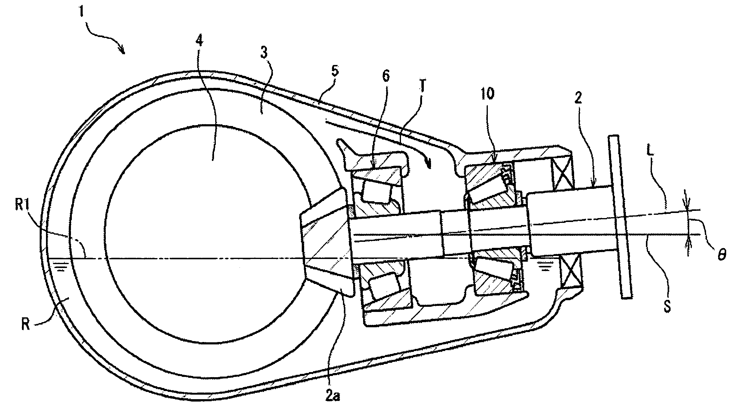
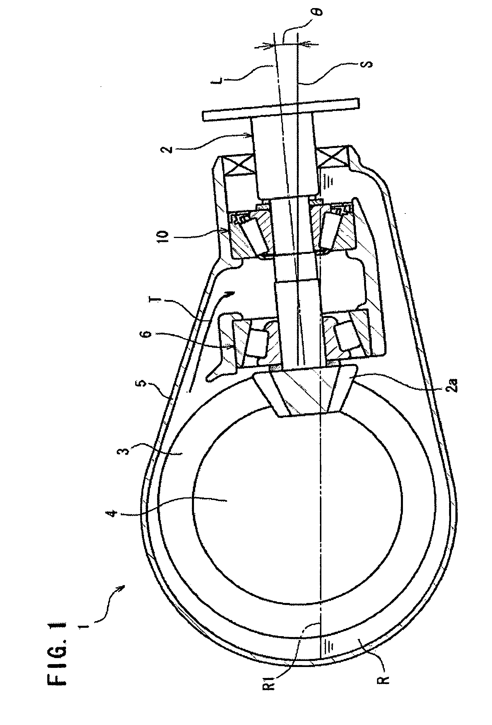
[0024]Next, a preferred embodiment of the invention is described with reference to the accompanying drawings. Incidentally, in the following description, the invention is described by exemplifying a case where the invention is applied to a differential device for rear-drive of an automobile. FIG. 1 is a cross-sectional view illustrating a differential device to which the invention is applied.

[0025]In FIG. 1, a differential device 1 is used for transmitting a turning force output from an engine (not shown) of an automobile to rear wheels (not shown) serving as driving wheels arranged at both sides (in a direction perpendicular to paper on which FIG. 1 is drawn) of the differential device 1. The differential device 1 includes a pinion shaft 2 connected to a propeller shaft (not shown) for transmitting an output of the engine integrally rotatably therewith, a ring gear 3 meshing with a pinion gear 2a provided at a one-end-side distal end of the pinion shaft 2, a differential mechanism ...


PUM


Abstract

A tapered roller bearing for a pinion shaft according to the invention includes an inner ring that has an outer circumferential surface on which an inner ring raceway surface is formed and that is integrally fixed to a one-end-side of the pinion shaft, an outer ring that has an inner circumferential surface on which an outer ring raceway surface is formed and that is fixed to a housing, and a plurality of tapered rollers rollably interposed between both of the raceway surfaces. An annular oil reservoir groove for storing lubricating oil is formed in a distal end portion at the one-end-side in an axial direction of the inner circumferential surface by being recessed thereinto adjacent to the outer ring raceway surface.

Description

BACKGROUND OF THE INVENTION[0001]The present invention relates to a tapered roller bearing apparatus for a pinion shaft, which is used for supporting a pinion shaft of a differential device of a vehicle or the like.[0002]A differential device used in rear wheel drive of a vehicle such as an automobile has a pinion shaft rotationally driven by being connected to a propeller shaft for transmitting an output of an engine, a ring gear that meshes with a pinion gear provided at a one-end-side distal end of this pinion shaft, and a differential mechanism fixed to this ring gear integrally rotatably therewith to rotate a pair of rear wheels. The differential device transmits an output of the engine, which is to be transmitted via the propeller shaft connected to the other-end side of the pinion shaft, to the pair of rear wheels.[0003]A pair of tapered roller bearings are placed at both end portions of the pinion shaft, respectively. The pinion shaft is rotatably supported in the housing of...

Claims


Application Information

Patent Timeline
Patent Type & Authority Applications(United States)
IPC IPC(8): F16C32/06F16C19/00
CPCF16C19/364F16C2361/61F16H2048/423F16C33/6651F16C19/548
Inventor MASUDA, NAOKIKODA, KANICHIKAWAGUCHI, TASHIHIRO
Owner JTEKT CORP
Why Eureka
Try Eureka