Fixing device and image forming apparatus including same

a technology of fixing device and image forming apparatus, which is applied in the direction of electrographic process apparatus, ohmic resistance heating, instruments, etc., can solve the problems of significant rise in parts of heaters, damage to nip portions, and unsuitable amount of force applied to the nip portion

Active Publication Date: 2009-08-20
RICOH KK
View PDF33 Cites 92 Cited by
  • Summary
  • Abstract
  • Description
  • Claims
  • Application Information

AI Technical Summary

Benefits of technology

[0018]Illustrative embodiments of the present invention provide a fixing device that is compact and achie

Problems solved by technology

A drawback to the foregoing configuration is that, because the heater heats the recording medium through the film member, an undesirable amount of force is applied to the nip portion when paper jams occur and/or the heater is damaged when a foreign substance accidentally enters the nip portion.
Furthermore, when the recording medium, the width of which is narrower than the width of the nip portion, passes through the nip portion, a temperature of end portions of the heater rises significantly because there is no media present thereat to absorb the heat thus generated, thereby damaging the heater.
In a case in which a primary current f

Method used


Image

  • Fixing device and image forming apparatus including same
  • Fixing device and image forming apparatus including same
  • Fixing device and image forming apparatus including same

Examples


embodiment 1

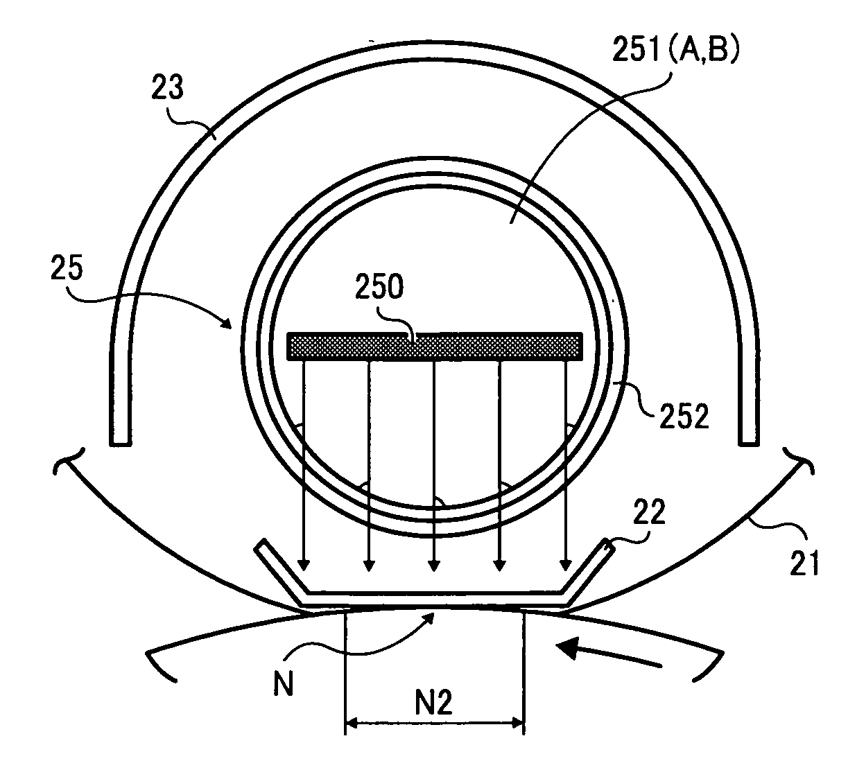
[0129]According to the illustrative embodiment, as illustrated in FIG. 7, the heating element 250 is formed of the carbon-based mold member consisting of a substantially long and thin sheet extending in the width direction W.

[0130]In FIG. 7, the heating element 250 includes a first flat planar surface 250A and a second flat planar surface 250B. The first planar surface 250A is disposed facing the reflective plate 23. The second planar surface 250B is disposed opposite the first planar surface 250A and faces the contact member 22.

[0131]When the heating element 250 is formed in the thin plate, the amount of the radiant heat at the first planar surface 250A side can be increased, thereby enabling the heat emitted from the infrared heater 25 to be directed intensively to the contact member 22.

[0132]As a result, the contact member 22 can be efficiently heated so that the rise time can be reduced using less power while stabilizing fixing performance and thus obtaining a quality image. In ...

embodiment 2

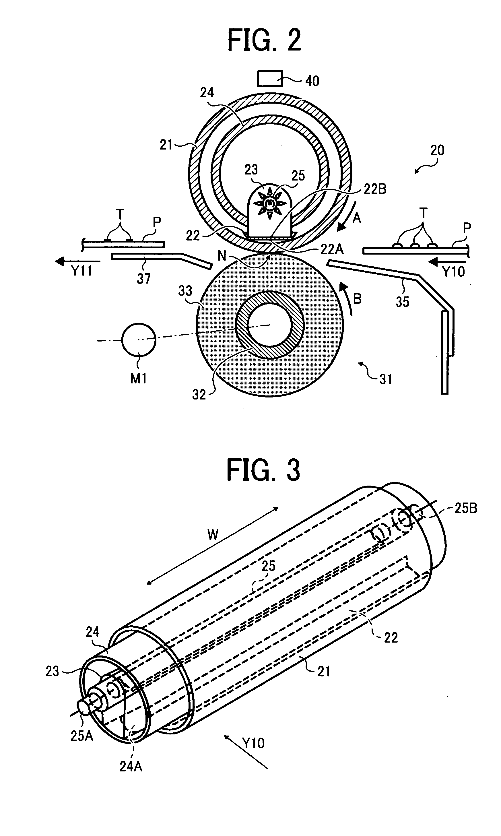
[0133]Referring now to FIGS. 8A and 8B, there are provided schematic diagrams illustrating the heating element 250 according to another embodiment.

[0134]The heating element 250 according to another embodiment is a thin plate member having a width W1 in the sheet width direction W greater than a nip length N1 of the nip portion N in the sheet width direction W.

[0135]Alternatively, as illustrated in FIG. 8B, a width W2 of the heating element 250 in the direction of sheet transport indicated by arrow Y10 substantially perpendicular to the sheet width direction W on the same plane of the width direction W is greater than a nip width N2 of the nip portion N.

[0136]With this configuration, when the width W1 of the heating element 250 is substantially greater than the nip length N1 or the width W2 of the heating element 250 is substantially greater than the nip width N2 of the nip portion N, the nip portion N can be evenly heated, thereby enhancing fixability.

embodiment 3

[0137]With reference FIGS. 9A through 9D, variations of the heating element 250 are described. In a case in which each of a plurality of sheets of the recording media P has the same sheet width and is transported in the fixing device 20, end portions 250C and 250D of the heating element 250 in the sheet width direction W, that is, the longitudinal direction of the heating element 250, may appear outside the retainer 24 as can be seen in FIG. 4.

[0138]In such a case, even if the heating element 250 is heated, some heat escapes from substantially the end portions 250C and 250D to outside the fixing film 21 and / or the retainer 24. Consequently, the end portions of the contact member 22 near the end portions 250C and 250D of the heating element 250 and / or the end portions of the fixing film 21 are not adequately heated, possibly causing fixing failure.

[0139]In view of the above, the amount of the radiant heat radiated from at least one end portion of the heating element 250 is configured...


PUM


Abstract

A fixing device includes a fixing member, a pressure member, a contact member, and a heater. The fixing member is provided in a width direction of a recording medium and to heat and fuse a toner image on the recording medium. The pressure member is to press against the fixing member. The contact member is provided inside the fixing member and to contact the pressure member through the fixing member to form a nip portion between the pressure member and the fixing member. The heater includes a heating element and is to heat the contact member. The heating element of the heater is a mold member of a relatively thin plate extending in a width direction of the fixing member and includes a flat surface that faces the contact member. An image forming apparatus for forming an image includes the fixing device.

Description

CROSS-REFERENCE TO RELATED APPLICATIONS[0001]This patent application is based on and claims priority pursuant to 35 U.S.C. §119 from Japanese Patent Application No. 2008-037308 filed on Feb. 19, 2008 in the Japan Patent Office, the entire contents of which are hereby incorporated herein by reference.BACKGROUND OF THE INVENTION[0002]1. Field of the Invention[0003]Exemplary aspects of the present invention generally relate to a fixing device and an image forming apparatus, such as a copier, a facsimile machine, a printer, or a multi-functional system including any combination thereof, and more particularly, to an image forming apparatus including the fixing device.[0004]2. Description of the Background Art[0005]A related art fixing device for an image forming apparatus, for example, that according to JP-H08-27571-B, is equipped with a heater, a film member that slidably moves with the heater, and a pressure member that is movable and presses against the heater through the film member....

Claims


Application Information

Patent Timeline
IPC IPC(8): G03G15/20
CPCG03G2215/2035G03G15/2064
Inventor FUJIWARA, HIDEHIKOBANNAI, KAZUNORI
Owner RICOH KK
Why Eureka
Try Eureka