Base station apparatus, communication terminal apparatus, and multicarrier communication method

a communication terminal and base station technology, applied in multiplex communication, orthogonal multiplex, signalling characterisation, etc., can solve the problems of increasing the amount of uplink overhead, reducing transmission efficiency, and increasing the amount of cqi information reported to the base station, so as to improve frequency efficiency and improve the throughput of the communication system

Inactive Publication Date: 2009-08-20
PANASONIC CORP
View PDF13 Cites 39 Cited by
  • Summary
  • Abstract
  • Description
  • Claims
  • Application Information

AI Technical Summary

Benefits of technology

[0009]The present invention can satisfy QoS and improve frequency efficiency and a communication system throughput.

Problems solved by technology

However, when this technique is applied to a multicarrier communication system with the high transmission rate such as OFDM (Orthogonal Frequency Division Multiplexing) the number of channels and the number of terminals accommodated increase, and so there is a problem that the amount of CQI information reported to the base station becomes enormous, the amount of uplink overhead increases and transmission efficiency decreases.

Method used


Image

  • Base station apparatus, communication terminal apparatus, and multicarrier communication method
  • Base station apparatus, communication terminal apparatus, and multicarrier communication method
  • Base station apparatus, communication terminal apparatus, and multicarrier communication method

Examples


embodiment 1

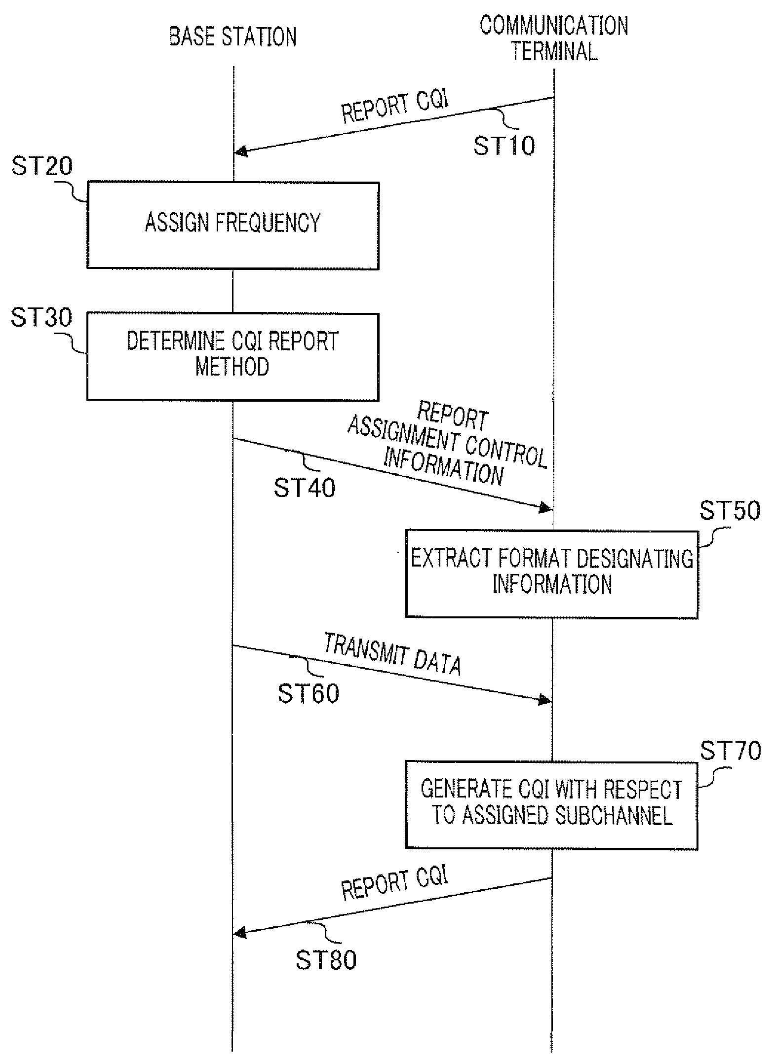
[0048]FIG. 1 is a block diagram showing a main configuration of a base station apparatus according to Embodiment 1 of the present invention. An example will be described here where the communication system transmits MCS parameters by selecting the parameters on a per subchannel basis in a closed-loop communication system. Further, a “subchannel” generally refers to a band formed with a single or a plurality of subcarriers and is a control unit for frequency scheduling (i.e. frequency assignment) and adaptive modulation.

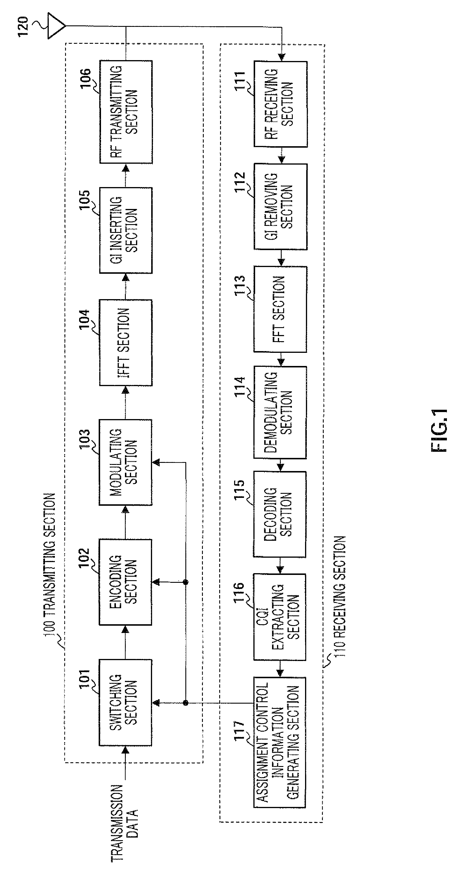
[0049]The base station apparatus according to this embodiment is formed mainly with transmitting section 100 and receiving section 110. Transmitting section 100 has switching section 101, encoding section 102, modulating section 103, IFFT section 104, GI inserting section 105 and RF transmitting section 106. Receiving section 110 has RF receiving section 111, GI removing section 112, FFT section 113, demodulating section 114, decoding section 115, CQI extracting secti...

embodiment 2

[0116]The base station apparatus according to Embodiment 2 of the present invention commands a communication terminal with a low transmission rate to report CQI's with respect to a predetermined number of subchannels with good received quality.

[0117]The basic configuration of the base station according to this embodiment is the same as the base station apparatus described in Embodiment 1, and so overlapping descriptions will be omitted and the assignment control information generating section with a different configuration will be described. Further, the basic configuration is the same, but reference numerals of components having a little difference in details will be assigned small letters in alphabet.

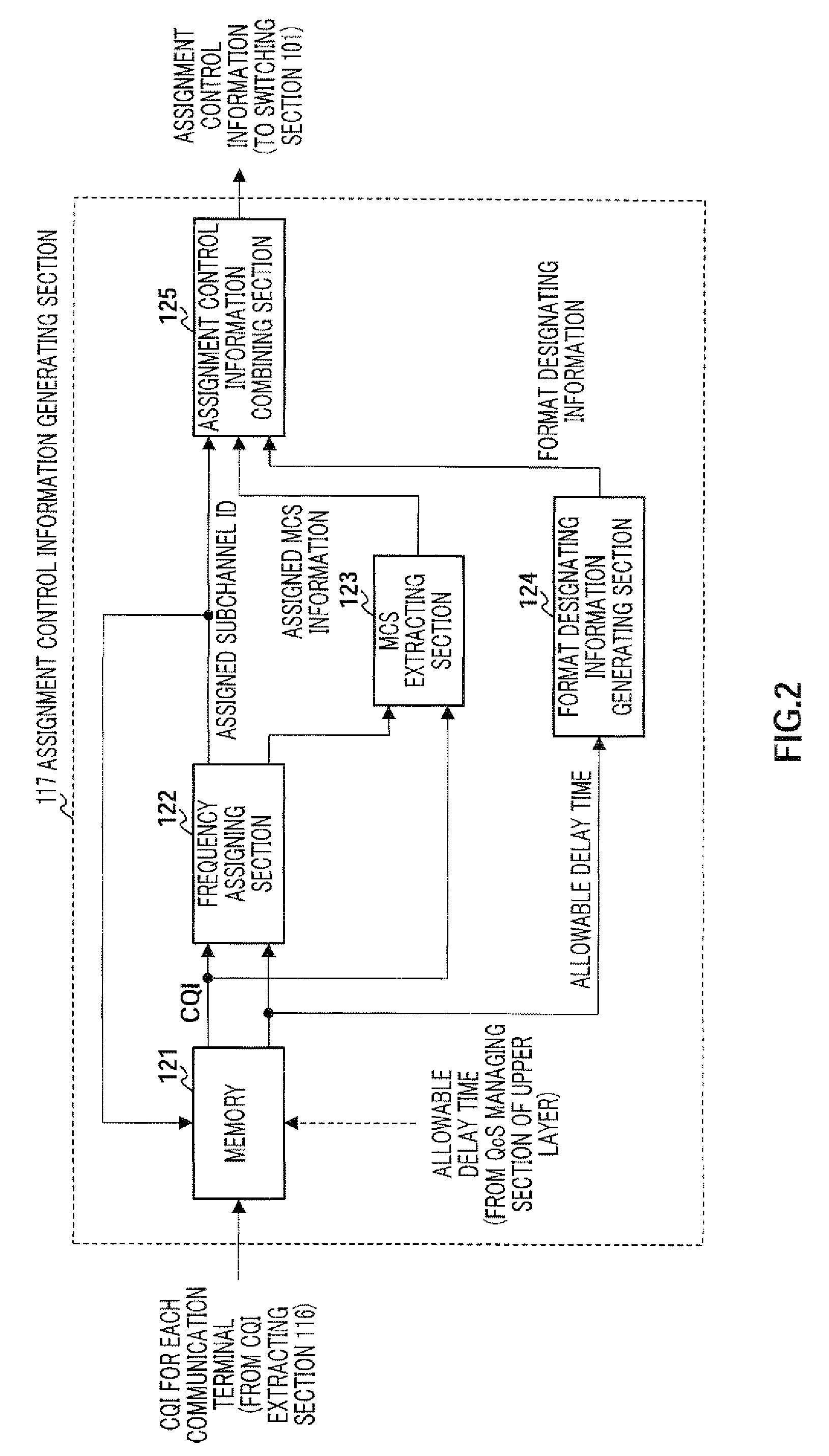
[0118]FIG. 16 is a block diagram showing a main configuration of assignment control information generating section 117a according to this embodiment. Further, assignment control information generating section 117a has the same basic configuration as assignment control information gene...

embodiment 3

[0152]The base station apparatus according to Embodiment 3 of the present invention includes more format designating information than the base station apparatus described in Embodiment 2, that is, more variations of CQI report methods.

[0153]To be more specific, in addition to Embodiment 2, in CQI report methods and format designating information, format designating information “3” for designating “the CQI report method for reporting CQI's with respect to subchannels already assigned and CQI's with respect to n subchannels with good quality outside the assigned band and format designating information “4” for designating “the CQI report method for reporting CQI's with respect to the save subchannels as in the previous CQI report” are further added.

[0154]Further, the base station apparatus according to this embodiment includes more variations in reception variation deciding information compared to Embodiment 2.

[0155]To be more specific, although reception variation deciding information...


PUM


Abstract

A multicarrier communication method capable of improving the frequency utilization efficiency and the throughput of the communication system, while satisfying the QoS. A communication terminal reports the CQI about all of the subchannels included in the bandwidth of a communication channel during a first CQI report, as shown in the upper figure portion. Unlike the first report, during the second and following CQI reports, in which much time is left in terms of the permissible delay time, the communication terminal reports the CQI only about subchannels 1 and 2 assigned by the second and following frequency assignments, as shown in the lower figure portion.

Description

TECHNICAL FIELD[0001]The present invention relates to a base station apparatus, communication terminal apparatus and multicarrier communication method.BACKGROUND ART[0002]In a radio communication system, to produce high throughput, there is a technique for reporting channel quality information referred to as “CQI” (Channel Quality Indicator) from a communication terminal to a base station and determining at the base station modulation parameters (MCS: Modulation Coding Scheme) upon transmission based on the reported CQI.[0003]However, when this technique is applied to a multicarrier communication system with the high transmission rate such as OFDM (Orthogonal Frequency Division Multiplexing) the number of channels and the number of terminals accommodated increase, and so there is a problem that the amount of CQI information reported to the base station becomes enormous, the amount of uplink overhead increases and transmission efficiency decreases.[0004]To solve this problem, Patent ...

Claims


Application Information

Patent Timeline
Patent Type & Authority Applications(United States)
IPC IPC(8): H04W72/08H04W28/24
CPCH04L1/0027H04W28/24H04L27/261H04L1/20H04J11/00
Inventor KURI, KENICHIIMAMURA, DAICHINISHIO, AKIHIKO
Owner PANASONIC CORP
Why Eureka
Try Eureka