Suction Retraction Surgical Instrument

a surgical instrument and suction technology, applied in the field of suction retraction surgical instruments, can solve the problems of not being able to safely hold on to the tissue, not being able to adapt to the purpose, and the cobb elevator is not able to firmly grasp the tissue, so as to achieve the effect of convenient instrument manipulation

Inactive Publication Date: 2009-08-20
SHELOKOV ALEXIS PAUL
View PDF12 Cites 9 Cited by
  • Summary
  • Abstract
  • Description
  • Claims
  • Application Information

AI Technical Summary

Benefits of technology

[0009]The instrument includes a suction connector at the proximal section of the elongate body. The suction connector is in communication with the vacuum channel. The suction connector is adapted to aid in communication with a vacuum system for removal of smoke, fluid and other matter from the surgical site. In one embodiment, the inner surface of the retractor is substantially concave and the outer surface of the retractor is substantially convex. The central section includes an enlarged region for easy manipulation of the instrument.

Problems solved by technology

While the Cobb elevator is currently being used to retract the tissue, it is not particularly adapted for that purpose.
There are several disadvantages associated with using the Cobb elevator to retract the tissue.
The Cobb elevator is not adapted to firmly grasp the tissue and has a tendency to slip due to the smooth nature of the blade.
The smooth nature of the blade makes it difficult to safely hold on to the tissue.
Furthermore, the Bovie cautery (or other electric knife) generates a significant amount of smoke and fluid (e.g., blood) at the surgical site.
The smoke is generated by superheating of the water in the tissue and some charring also occurs in denser tissue creating debris.
The accumulation of smoke and fluid obstructs the vision of the operating surgeon.
In a limited space (i.e., the surgical site), the presence of two instruments complicates the procedure and makes the manipulation of the instruments difficult.

Method used


Image

  • Suction Retraction Surgical Instrument
  • Suction Retraction Surgical Instrument
  • Suction Retraction Surgical Instrument

Examples


Embodiment Construction

[0016]The various features and methods of the suction retraction surgical instrument will now be described. Those skilled in the art will recognize that the instrument can be used in spinal and other types of surgery.

[0017]Throughout the description, implementation-specific details will be given on how the instrument is used. These details are provided to illustrate the preferred embodiments of the invention and not to limit the scope of the invention. The scope of the invention is set in the claims section.

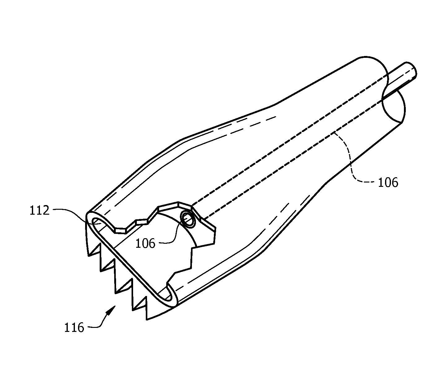
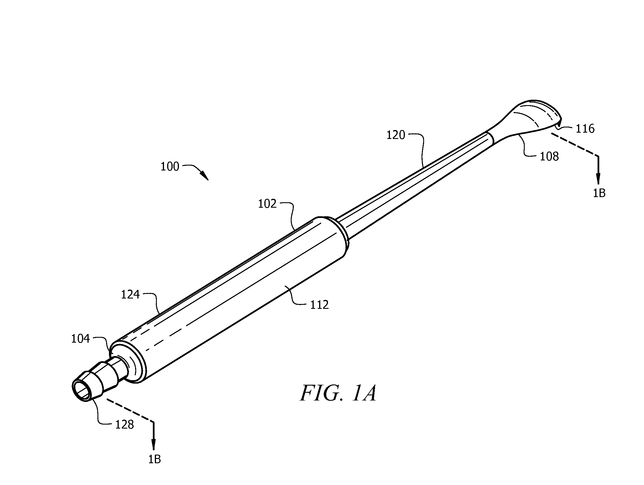
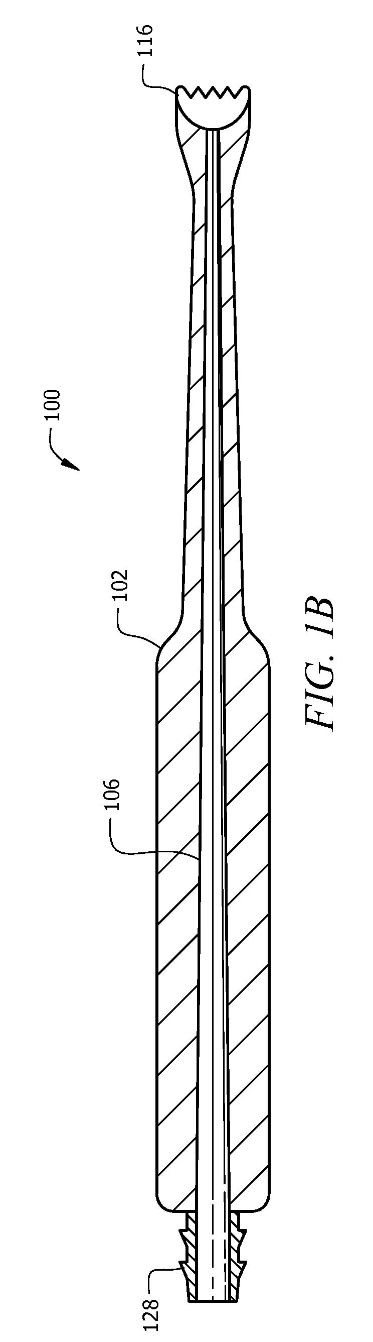
[0018]FIG. 1A illustrates one embodiment of a suction retraction surgical instrument 100. The surgical instrument 100 includes an elongate body 102 having a proximal section 104, a distal section 108 and a central section 112. A vacuum or suction channel 106 shown in FIG. 1B is defined within the elongate body 102. The channel 106 provides a path for smoke, fluid (e.g., blood) and other matter (e.g., debris) to be removed from a surgical site.

[0019]A curved retractor 116 is locat...


PUM


Abstract

A suction retraction surgical instrument retracts tissue and removes smoke, fluid, debris and other matter from a surgical site. The instrument includes an elongate body having a proximal section, a distal section and a central section. A vacuum or suction channel is defined within the elongate body. The instrument includes a retractor at the distal section of the elongate body. The retractor has an inner surface and an outer surface defining a suction port. The suction port is adapted to remove smoke, blood and other matter from the surgical site. The instrument includes a suction connector at the proximal section of the elongate body. The suction connector is in communication with the vacuum channel. The suction connector is adapted to aid in communication with a vacuum system for removal of smoke, fluid and other matter from the surgical site.

Description

[0001]This invention relates to surgical instruments and, more particularly, to a suction retraction surgical instrument for retracting tissue and for removing matter from a surgical site.BACKGROUND OF THE INVENTION[0002]In spinal and other surgery, the tissue is divided from the bone using a Bovie cautery or an electric knife. As the tissue is divided from the bone, the tissue is retracted. At present, a Cobb elevator is generally used by surgeons to retract the tissue.[0003]The Cobb elevator consists of a smooth blade at the tip of an elongated handle. The blade is used to displace the tissue laterally. While some surgeons scrape muscle from the bone with the Cobb elevator, most simply retract the muscle using the Cobb elevator and use the Bovie cautery to divide the muscle from the bone.[0004]While the Cobb elevator is currently being used to retract the tissue, it is not particularly adapted for that purpose. There are several disadvantages associated with using the Cobb elevato...

Claims


Application Information

Patent Timeline
Patent Type & Authority Applications(United States)
IPC IPC(8): A61B1/32A61M1/00
CPCA61B17/02A61M1/008A61M1/0039A61M1/76A61M1/84
Inventor SHELOKOV, ALEXIS PAUL
Owner SHELOKOV ALEXIS PAUL
Why Eureka
Try Eureka