Method of Detecting Dispensed Quantity, and Liquid Suction Monitoring Dispensing Apparatus

a technology of liquid suction and quantity detection, which is applied in the direction of liquid/fluent solid measurement, laboratory glassware, instruments, etc., can solve the problems of processing time loss, deficiency detection during the suction step cannot be carried out, and loss of processing tim

Active Publication Date: 2009-08-27
UNIVERSAL BIO RESEARCH CO LTD
View PDF10 Cites 12 Cited by
  • Summary
  • Abstract
  • Description
  • Claims
  • Application Information

AI Technical Summary

Problems solved by technology

(1) The liquid that was suctioned during liquid surface detection needs to be removed from the inside of the pipette tip.
(2) Since the lower end of the pipette tip needs to be lowered so as to conform to the liquid surface while suctioning air, the suctioning step and the lifting and lowering step need to be controlled simultaneously.
(3) In order to carry out the step of detecting the liquid surface first, even if the liquid is not accommodated within the container, lowering of the pipette tip and air suction need to be continued for a certain period of time. On the other hand, in the case where there is sufficient liquid present, deficiency detection during the suction step cannot be carried out.
(4) Since the conventional apparatus is dependent on the shape of the container, a liquid surface-liquid volume conversion table needs to be prepared for each of the container shapes.
(5) Conversion calculation needs to be performed within the processing time, resulting in a loss of processing time. Moreover, the processing time for the step for removing the liquid after detecting the liquid surface becomes a loss of time.
(6) Having detected the liquid surface, if the attached liquid is suctioned into the pipette tip again, then it can be falsely detected as liquid surface detection, resulting in a malfunction.
(7) In the case where bubbles have occurred on the liquid surface, the bubbles may be detected as a liquid surface, giving a false liquid surface detection, resulting in a malfunction.
(8) Since the liquid cannot be completely removed from the distal end of the pipette tip once the pipette tip has been used, a malfunction may occur in the case of reuse or continuous use of the pipette tip.
As mentioned above, a number of problems are observed.

Method used


Image

  • Method of Detecting Dispensed Quantity, and Liquid Suction Monitoring Dispensing Apparatus
  • Method of Detecting Dispensed Quantity, and Liquid Suction Monitoring Dispensing Apparatus
  • Method of Detecting Dispensed Quantity, and Liquid Suction Monitoring Dispensing Apparatus

Examples


Embodiment Construction

[0028]Hereinafter, an embodiment of the present invention is specifically described.

[0029]However, the present embodiment is to give a specific description with a purpose of providing better understanding of the intent of the present invention, and does not limit the content of the invention unless otherwise specified.

[0030][Configuration]

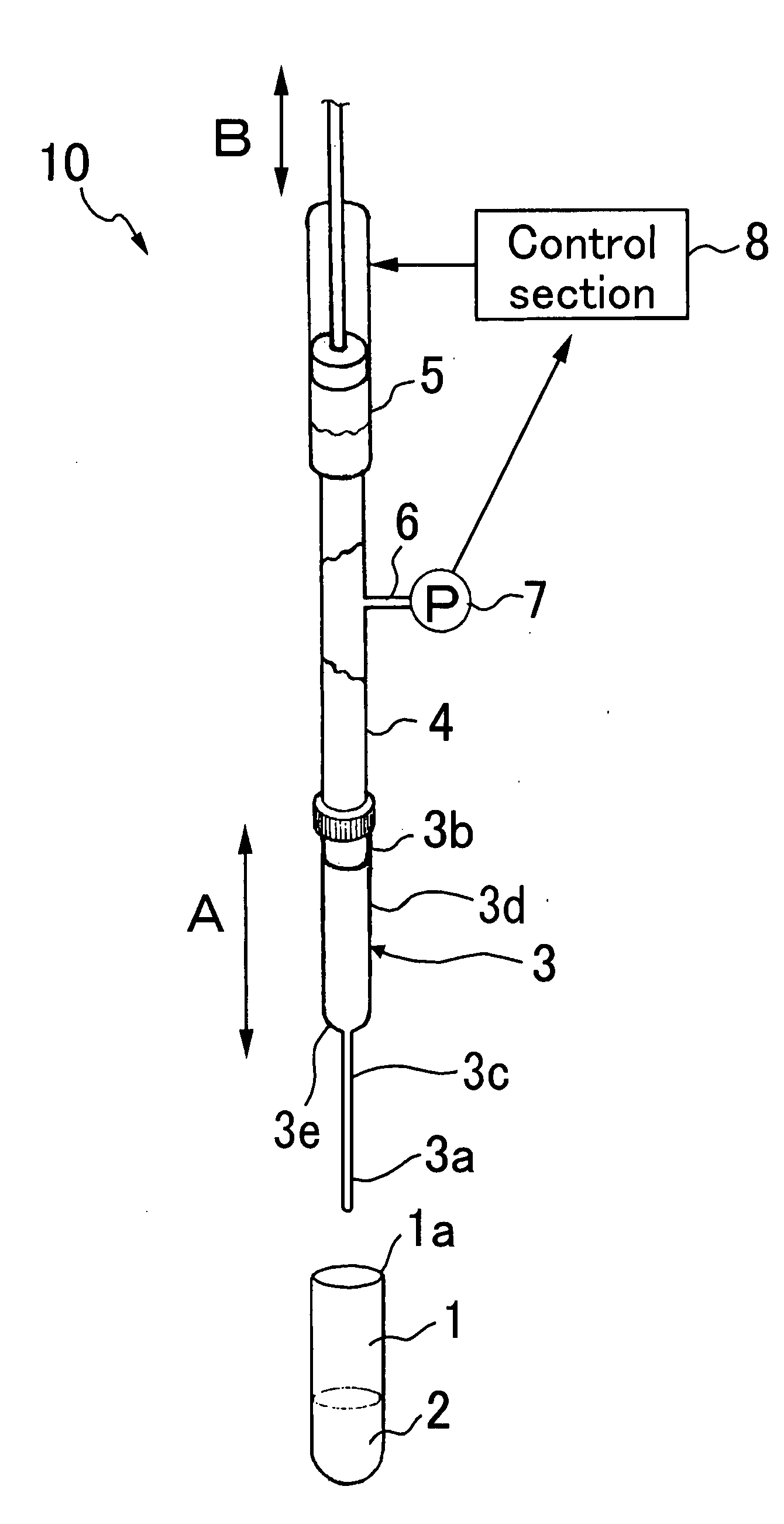
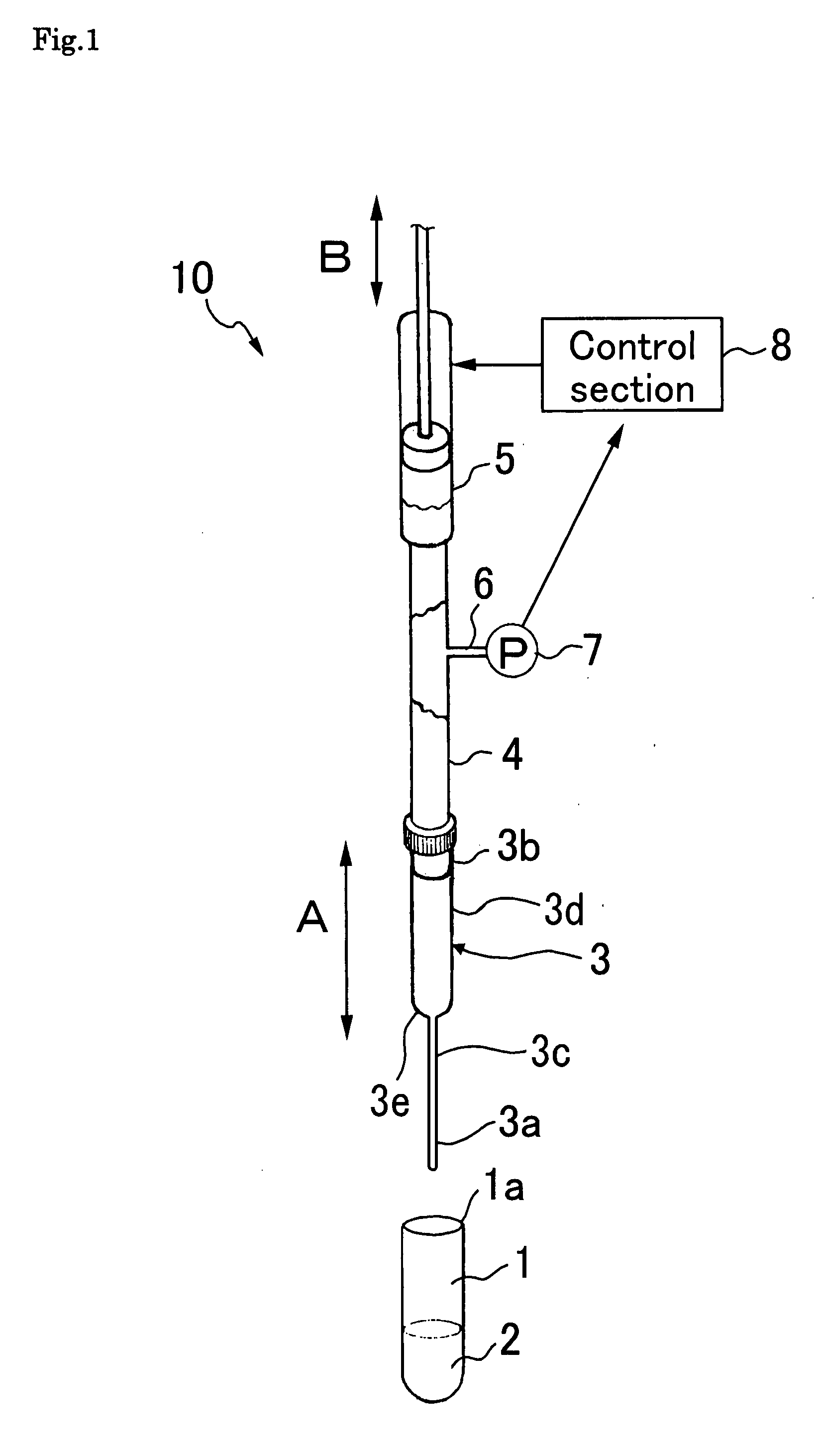
[0031]As shown in FIG. 1, a pipetter 10 of the present embodiment is provided with: a pipette tip 3 which is supported substantially vertically immediately above an opening section 1a of a container 1, and a distal end section (bottom end section) 3a of which is to be inserted into liquid accommodated in the container 1; a nozzle member 4 that is fitted on a top end section 3b of this pipette tip 3; a cylindrical suctioning / discharging mechanism 5 directly connected to this nozzle member 4; and a pressure sensor 7 that is connected to a side wall of the nozzle member 4 via a pipe or air hose 6. The distal end section 3a of the pipette tip 3 is prov...


PUM

PropertyMeasurementUnit
distanceaaaaaaaaaa
pressureaaaaaaaaaa
pressureaaaaaaaaaa

Abstract

There are provided a method of detecting dispensed quantity in which without the need of detecting a surface of liquid accommodated in a container, a liquid quantity can be detected only by measuring pressure change; and a relevant liquid suction monitoring dispensing apparatus. There is provided a method of detecting dispensed quantity for detection of the quantity of liquid suctioned and discharged by a dispensing apparatus including a pipette tip, a liquid suctioning/discharging mechanism for the pipette tip, a pressure sensor capable of detecting the pressure within the pipette tip, and a lifting and lowering mechanism for the pipette tip, which method comprises: an insertion step for inserting a distal end of the pipette tip down to the deepest zone of a container accommodating liquid to be measured; a suction pressure measuring step for without moving of the pipette tip, while suctioning the liquid into the pipette tip at a predetermined suctioning rate, measuring any pressure change during the suctioning; and a suction detecting step for on the basis of pressure change measured, determining the state of suction. Further, there is provided a liquid suction monitoring dispensing apparatus capable of practicing this method.

Description

TECHNICAL FIELD[0001]The present invention relates to a method of detecting dispensed quantity which uses changes in air pressure to detect a suction quantity of liquid, and a liquid quantity monitoring dispensing apparatus, in particular, to a method of monitoring liquid quantity detection based on changes in suction pressure in a dispensing apparatus that suctions liquid suspended with biological material into a pipette tip and dispenses the liquid into an examination container, and to an apparatus that employs this method.BACKGROUND ART[0002]Conventionally, there has been a dispensing method in which a suction quantity is detected and evaluated by suctioning liquid from a container into a pipette tip with a dispensing apparatus (Patent Document 1). In this dispensing method,(a) when the lower end of a measuring instrument is immersed into liquid to be suctioned by a relative vertical movement between the measuring instrument and a container accommodating the liquid to be suctione...

Claims


Application Information

Patent Timeline
Patent Type & Authority Applications(United States)
IPC IPC(8): G01N1/14B01L3/02
CPCG01N2035/1025G01N35/1016
Inventor TAJIMA, HIDEJIKOIZUKA, MICHINORISUZUKI, HIROSHIKIMURA, SUSUMU
Owner UNIVERSAL BIO RESEARCH CO LTD
Why Eureka
Try Eureka