Dual power pin connector assembly for a mig welding machine

a technology of power pins and connectors, applied in the direction of welding apparatus, electrode supporting devices, manufacturing tools, etc., can solve the problems of laborious and time-consuming, aluminum wire electrodes can easily be damaged, and the standard wire drive may not be suitable, so as to achieve the effect of quick connection or disconnection of the spool gun

Active Publication Date: 2009-08-27
ILLINOIS TOOL WORKS INC
View PDF14 Cites 17 Cited by
  • Summary
  • Abstract
  • Description
  • Claims
  • Application Information

AI Technical Summary

Benefits of technology

[0027]In accordance with still another aspect of the present invention, a method of quickly connecting or disconnecting a spoolgun to a welding machine is provided. The method includes providing a conductive dual power pin connector having a clamping assembly, securing one end of the connector to a welding power terminal, securing a second end of the connector to a wire drive that feeds a consumable wire electrode to a MIG gun, and securing one end of a spoolgun power supply cable to the connector via the clamping assembly.

Problems solved by technology

In other welding-type applications, for example, MIG welding with a consumable aluminum wire electrode, the standard wire drive may not be suitable.
Aluminum wire electrodes can easily be damaged by equipment otherwise acceptable for steel wire electrodes.
It is labor intensive and time consuming to add or remove a spoolgun 42 in this manner.
Further, repeated tightening and loosening of the nut 50 may cause operational problems.
For example, the nut 50 may not be tightened sufficiently and work itself loose over time.
Still further, tools, such as wrenches and the like, are easily misplaced or lost resulting in time wasted while looking for a suitable tool to loosen the nut 50 from the power terminal 16.
Even this practice has drawbacks, however.
A number of prior art systems require special connectors and unique cable assemblies that cannot be used on existing welding machines.
However, one drawback to this and similar prior art devices is that these mechanisms will not work on existing spoolguns or welding machines without substantial modifications, if at all.

Method used


Image

  • Dual power pin connector assembly for a mig welding machine
  • Dual power pin connector assembly for a mig welding machine
  • Dual power pin connector assembly for a mig welding machine

Examples


Embodiment Construction

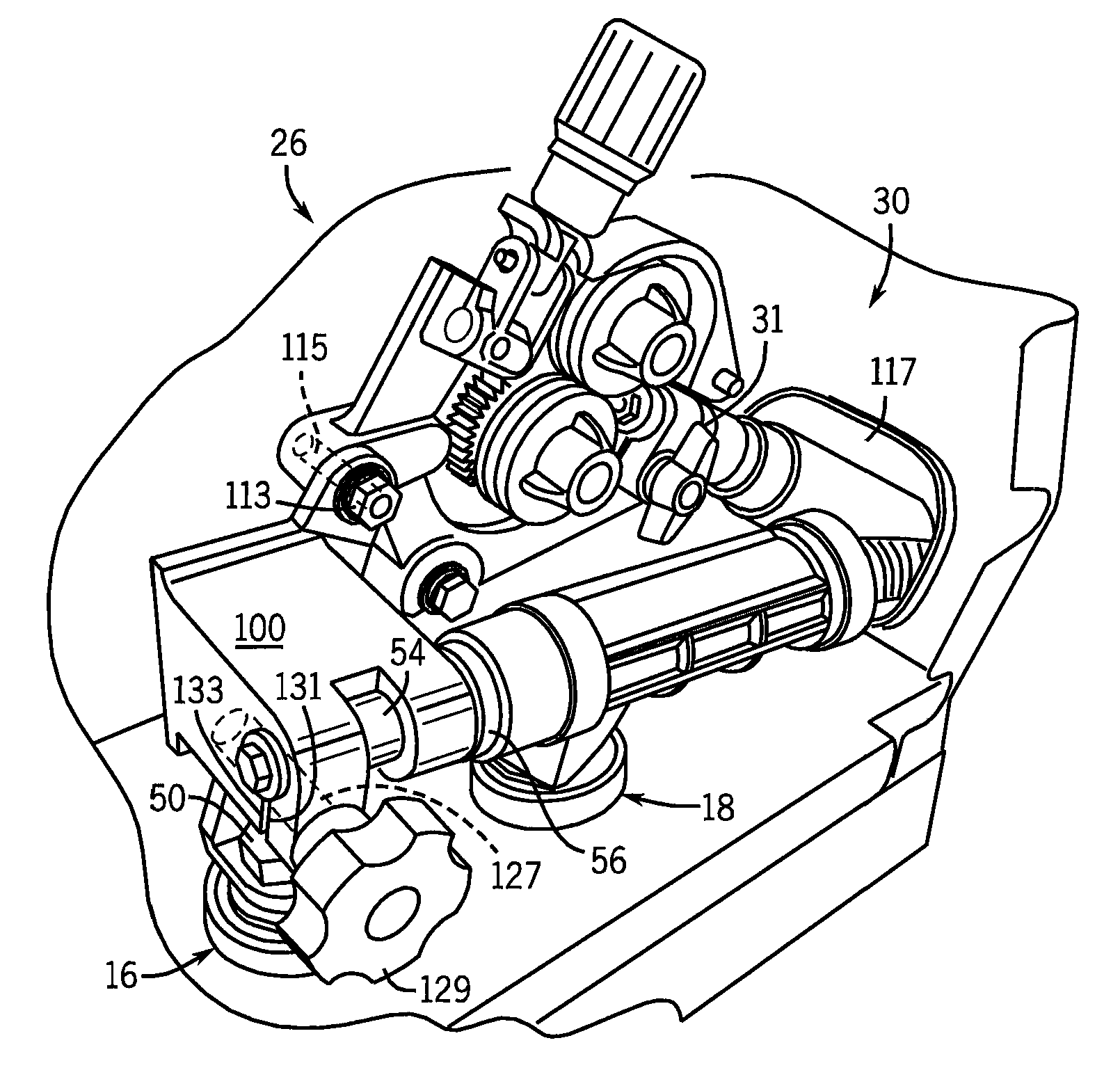
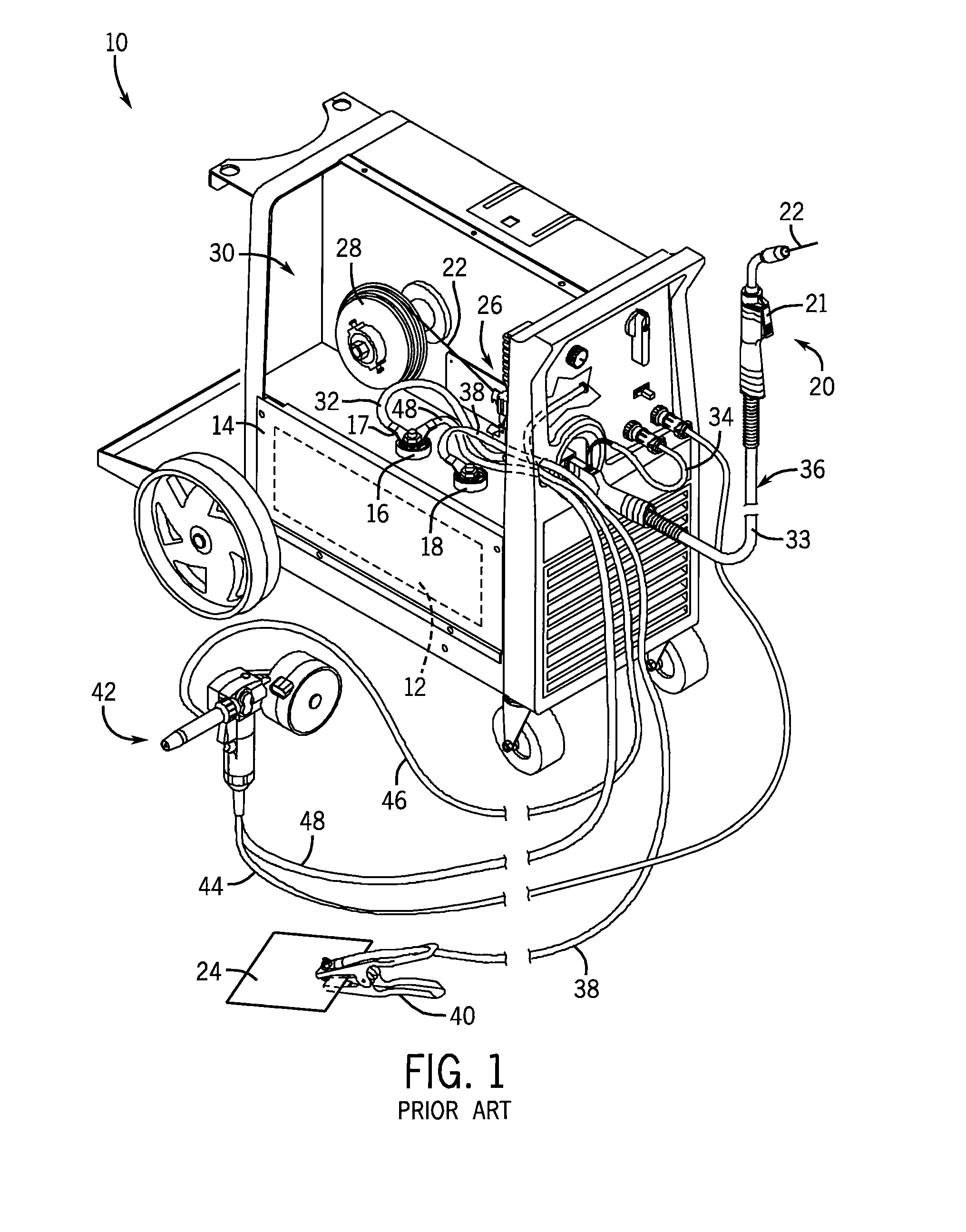
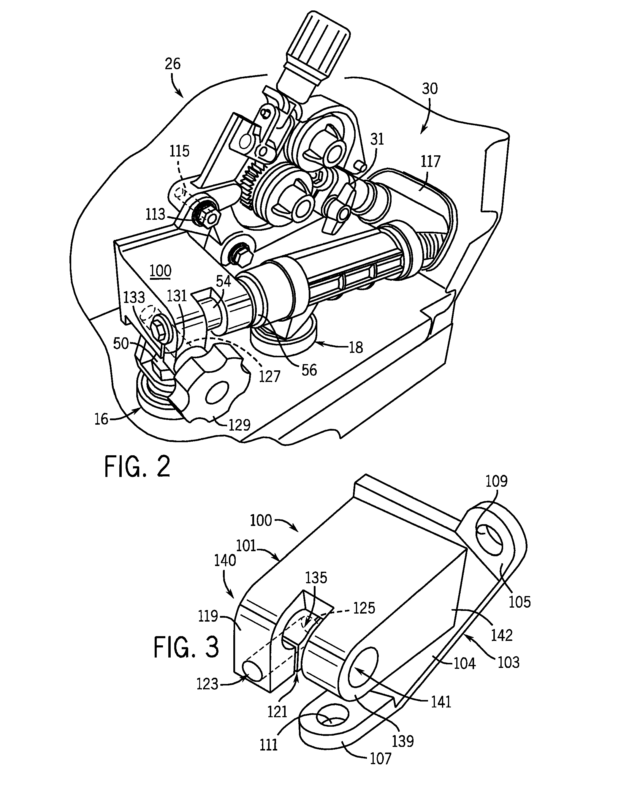
[0036]While still referring to several of the components of the welding machine 10 of FIG. 1, a dual power-pin connector assembly, or power bridge, 100 is shown in FIGS. 2-5 that enables at least two welding implements to be connected to the welding machine 10 at the same time. The dual power-pin connector 100 is cast or machined from an electrically conductive material such as steel, copper, or the like. In one embodiment, the connector 100 electrically couples the positive welding power terminal 16 to a first welding implement, for example, MIG welding gun 20, via a conductive path that includes the connector 100, the automatic wire drive or feeder 26, the power pin 31 and the consumable wire electrode 22. The connector 100 also electrically couples the terminal 16 to a second welding implement, for example spoolgun 42, via a conductive path that includes the connector 100, spoolgun power pin 54 and spoolgun power supply cable 48.

[0037]According to the embodiment shown, the dual p...


PUM

PropertyMeasurementUnit
distanceaaaaaaaaaa
lengthaaaaaaaaaa
poweraaaaaaaaaa

Abstract

A dual power pin connector assembly for connecting both a MIG welding gun and a spoolgun to a welding machine. The dual power pin connector is comprised of a busbar portion that electrically and mechanically couples the positive output terminal of the welding machine power supply to a wire drive for the MIG welding gun. The connector is further comprised of an integral quick release assembly/clamping portion that electrically and mechanically connects the positive power supply terminal to a power supply cable for the spoolgun. The clamping portion receives and retains a power pin coupled to one end of the spoolgun power cable in a receptacle that is manually tightened and loosened.

Description

REFERENCE TO RELATED APPLICATIONS[0001]Not applicable.STATEMENT REGARDING FEDERALLY SPONSORED RESEARCH OR DEVELOPMENT[0002]Not applicable.BACKGROUND OF THE INVENTION[0003]The present invention relates generally to welding-type systems and, more particularly, to an apparatus that provides welding-type power to a MIG welding gun while also providing a quick and easy means for supplying welding-type power to a spoolgun.[0004]There are many welding-type systems used for a variety of applications. The term “welding-type systems”, as used herein, includes arc welding systems, plasma cutting systems, and induction heating systems. Accordingly, the term “welding-type power”, as used herein, may refer to welding, plasma cutting, or induction heating power. One primary component of all welding-type systems is a power supply that delivers conditioned welding-type power to perform a specific welding-type process.[0005]Some welding-type applications, such as steel arc welding, utilize a motor dr...

Claims


Application Information

Patent Timeline
Patent Type & Authority Applications(United States)
IPC IPC(8): B23K9/28B23K9/133B23K9/32
CPCY10T29/49002B23K9/1336
Inventor WILLENKAMP, ROBERTROZMARYNOWSKI, SCOTT
Owner ILLINOIS TOOL WORKS INC
Why Eureka
Try Eureka