
Visually tracking an object in real world using 2d appearance and multicue depth estimations

Inactive Publication Date: 2009-08-27
HONDA RES INST EUROPE
View PDF7 Cites 48 Cited by
  • Summary
  • Abstract
  • Description
  • Claims
  • Application Information

AI Technical Summary

Benefits of technology

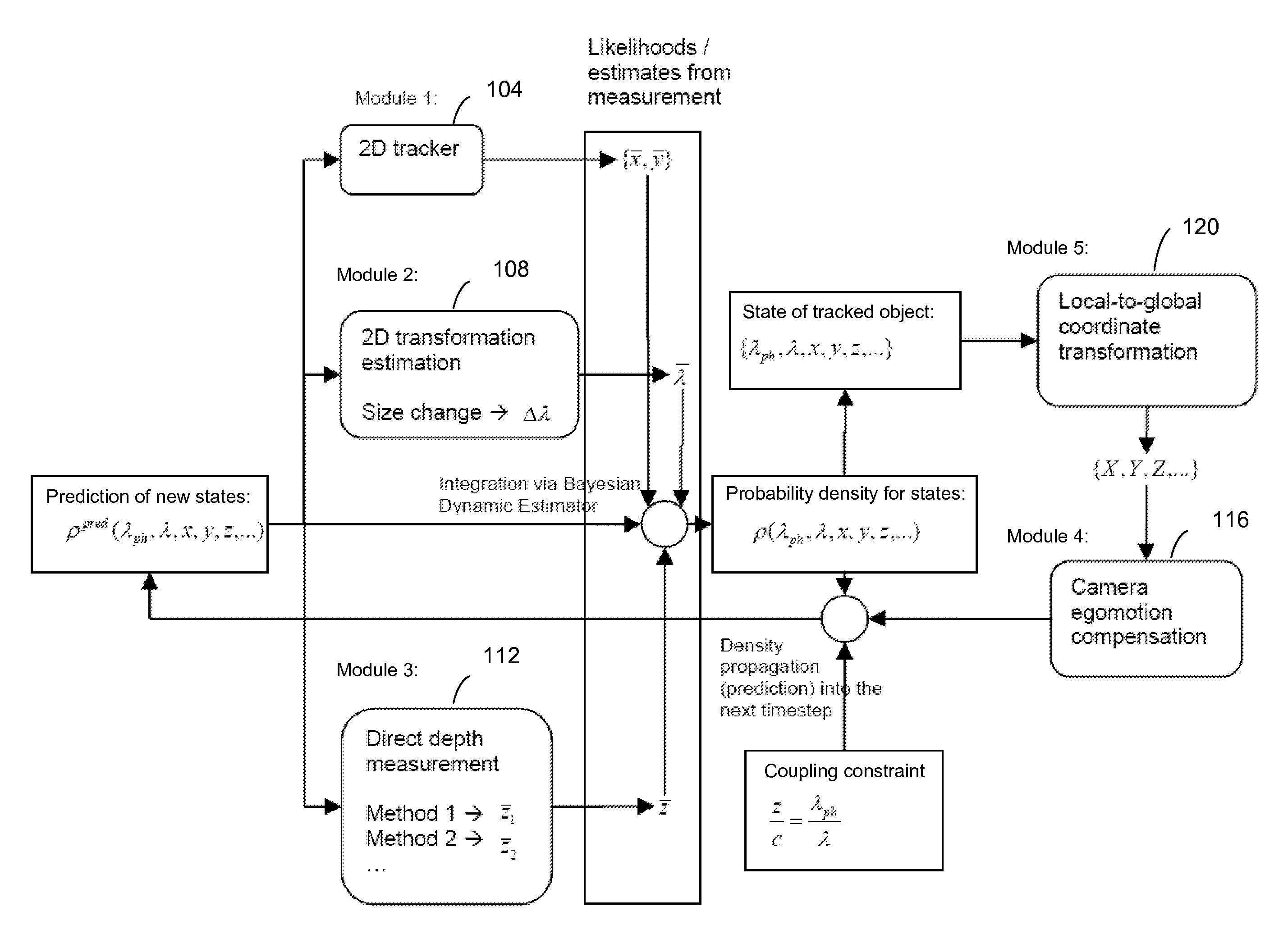
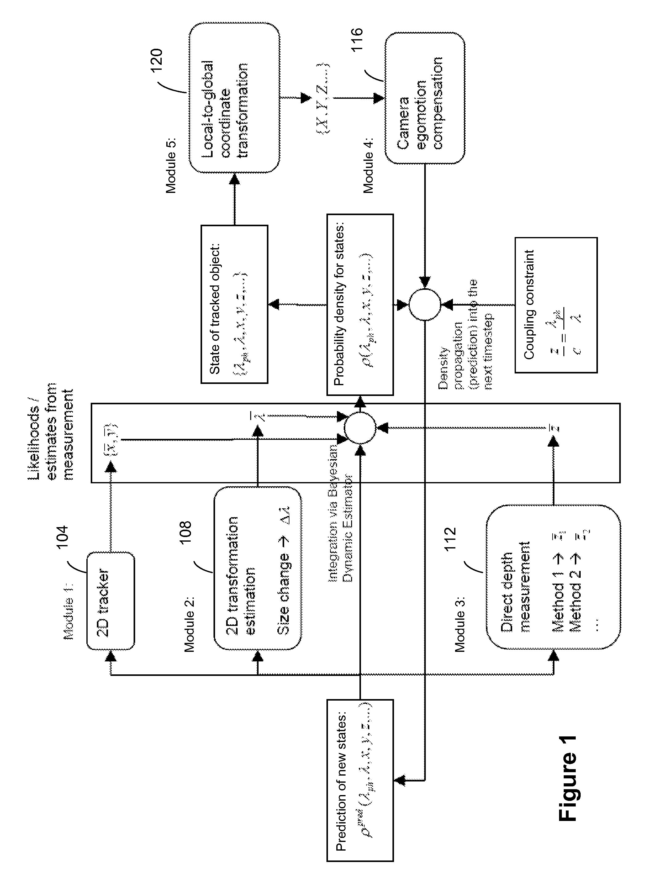
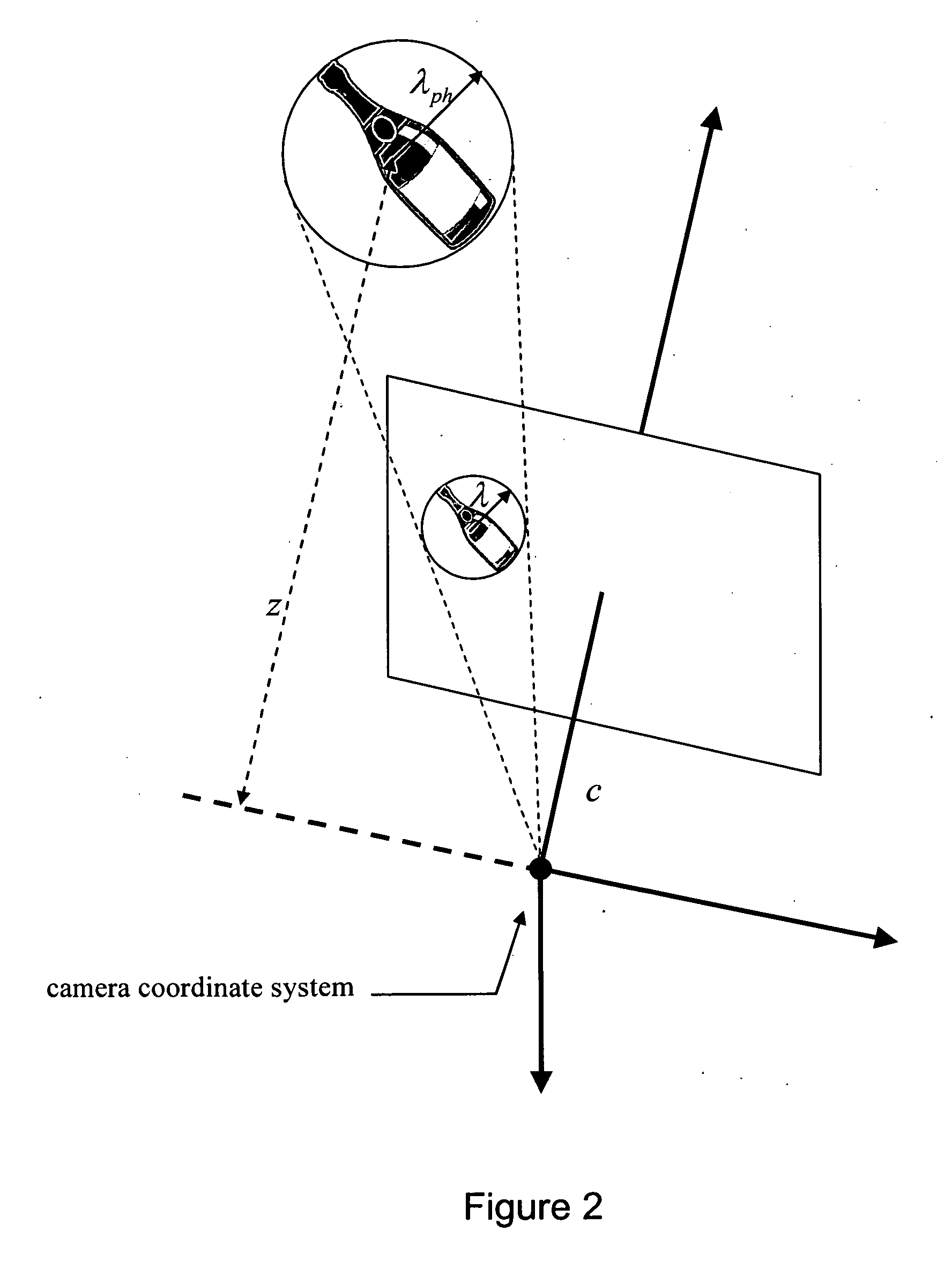
[0010]In one embodiment, an estimation of the depth and the depth change of the object coupled with the change in the scale or size of the object improves the depth estimation for the object. For rigid objects, a decrease or an increase in size serves as an indicator for an increase or decrease in the depth of an object,

Problems solved by technology

One of the problems in tracking systems is the need for accurate internal models of the objects being tracked.
In a general case, however, objects to be tracked are not determined in advance and therefore accurate 3D model or other specific information is unavailable.

Method used


Image

  • Visually tracking an object in real world using 2d appearance and multicue depth estimations
  • Visually tracking an object in real world using 2d appearance and multicue depth estimations
  • Visually tracking an object in real world using 2d appearance and multicue depth estimations

Examples


Embodiment Construction

[0022]A preferred embodiment of the present invention is now described with reference to the figures where like reference numbers indicate identical or functionally similar elements.

[0023]Reference in the specification to “one embodiment” or to “an embodiment” means that a particular feature, structure, or characteristic described in connection with the embodiments is included in at least one embodiment of the invention. The appearances of the phrase “in one embodiment” in various places in the specification are not necessarily all referring to the same embodiment.

[0024]Some portions of the detailed description that follows are presented in terms of algorithms and symbolic representations of operations on data bits within a computer memory. These algorithmic descriptions and representations are the means used by those skilled in the data processing arts to most effectively convey the substance of their work to others skilled in the art. An algorithm is here, and generally, conceived...


PUM


Abstract

Estimating the dynamic states of a real-world object over time using a camera, two dimensional (2D) image information and a combination of different measurements of the distance between the object and the camera. The 2D image information is used to track a 2D position of the object as well as its 2D size of the appearance and change in the 2D size of the appearance of the object. In addition, the distance between the object and the camera is obtained from one or more direct depth measurements. The 2D position, the 2D size, and the depth of the object are coupled to obtain an improved estimation of three dimensional (3D) position and 3D velocity of the object. The object tracking apparatus uses the improved estimation to track real-world objects. The object tracking apparatus may be used on a moving platform such as a robot or a car with mounted cameras for a dynamic visual scene analysis.

Description

RELATED APPLICATIONS[0001]This application claims priority under 35 U.S.C. § 119(a) to European Patent Application number 07 122 829, filed on Dec. 11, 2007, which is incorporated by reference herein in its entirety.FIELD OF THE INVENTION[0002]The present invention relates to a method, a tracking apparatus and a computing device for estimating the dynamic state of a real-world object over time using a camera, two dimensional image information and measurements of the distance from the camera to the object.BACKGROUND OF THE INVENTION[0003]For various systems, visual tracking is one of the key features necessary for analyzing objects in dynamic environments. The visual tracking has been intensively researched during the last decade, leading to applications, for example, in the field of surveillance, collision avoidance and trajectory evaluation.[0004]As described in detail in Aaron Edsinger and Charles C. Kemp, “Toward Robot Learning of Tool Manipulation from Human Demonstration,” Comp...

Claims


Application Information

Patent Timeline
IPC IPC(8): H04N7/18G06K9/00
CPCG06T7/2086G06T7/208G06T7/277G06T7/285
Inventor EGGERT, JULIANREBHAN, SVENWILLERT, VOLKERZHANG, CHEN
Owner HONDA RES INST EUROPE
Learn More