Kneading disc segment and twin-screw extruder

Active Publication Date: 2009-08-27
KOBE STEEL LTD
View PDF2 Cites 8 Cited by
  • Summary
  • Abstract
  • Description
  • Claims
  • Application Information

AI Technical Summary

Benefits of technology

[0014]When the neutral kneading disc segment is seen in its section perpendicular to the axis, there is a large gap between adjacent kneading discs, so that during kneading, the material to be kneaded is apt to move (drop out) to the downstream side in a state of being not fully kneaded by the succeeding kneading disc. Therefore, in order to enhance the degree of kneading to a satisfactory extent, the present inventors thought it is necessary to effect kneading concentratedly before the movement of the material. Then it has been found out that the degree of kneading is improved by disposing the kneading discs in such a manner as the adjacent gaps narrowing with each other. In this way the present invention has been completed.
[0015]More specifically, if the second kneading disc having a phase difference δ of an acute angle relative to the first kneading disc is disposed so as to make up for the gap between the adjacent first kneading discs and if plural such disc sets are disposed continuously in the axial direction of the kneading screw as described above, it is possible to suppress drop-out of the material from the gap and thereby possible to knead the material in a concentrated manner, thus making it possible to afford a higher degree of kneading than in the conventional neutral kneading disc segment.
[0016]The above kneading disc segment according to the present invention is characterized in that the first kneading discs in the plural continuous disc sets have a phase difference of 180° with each other, in other words, the first kneading disc in a downstream-side disc set in the plural continuous disc sets has a phase difference of (180-δ)° relative to the second kneading disc in an upstream-side disc set. Therefore, kneading discs are never arranged continuously with an equal phase difference (with an equal gap) and there scarcely occurs any feed capacity for the material. Consequently, in these kneading disc segments, the material is easy to stay in the kneading section and becomes easy to be kneaded concentratedly. As a result, kneading is performed to a satisfactory extent and the degree of kneading can be improved remarkably.
[0017]It is preferable that the phase difference be in the range of 30° to 68°, thereby the material is easy to stay in the kneading section and the drop-out thereof is sure to be prevented, thus making it possible to enhance the degree of kneading.
[0018]Further, in a twin-screw extruder equipped with two co-rotating intermeshed type kneading screws each having the aforesaid kneading segment, it becomes easy to obtain a high degree of kneading.
[0019]With the kneading disc segment according to the present invention, it is possible to obtain a higher degree of kneading than in the conventional neutral kneading disc segment.

Problems solved by technology

On the other hand, the neutral kneading disc segment has scarcely any feed capacity for the material.
The neutral kneading disc segment disclosed in the above Japanese patent laid-open publication No. 2003-245534 possesses a high kneading capacity as noted above, but even the degree of kneading attained by using the neutral kneading disc segment is not satisfactory in comparison with the degree of kneading required recently.

Method used


Image

  • Kneading disc segment and twin-screw extruder
  • Kneading disc segment and twin-screw extruder
  • Kneading disc segment and twin-screw extruder

Examples


first embodiment

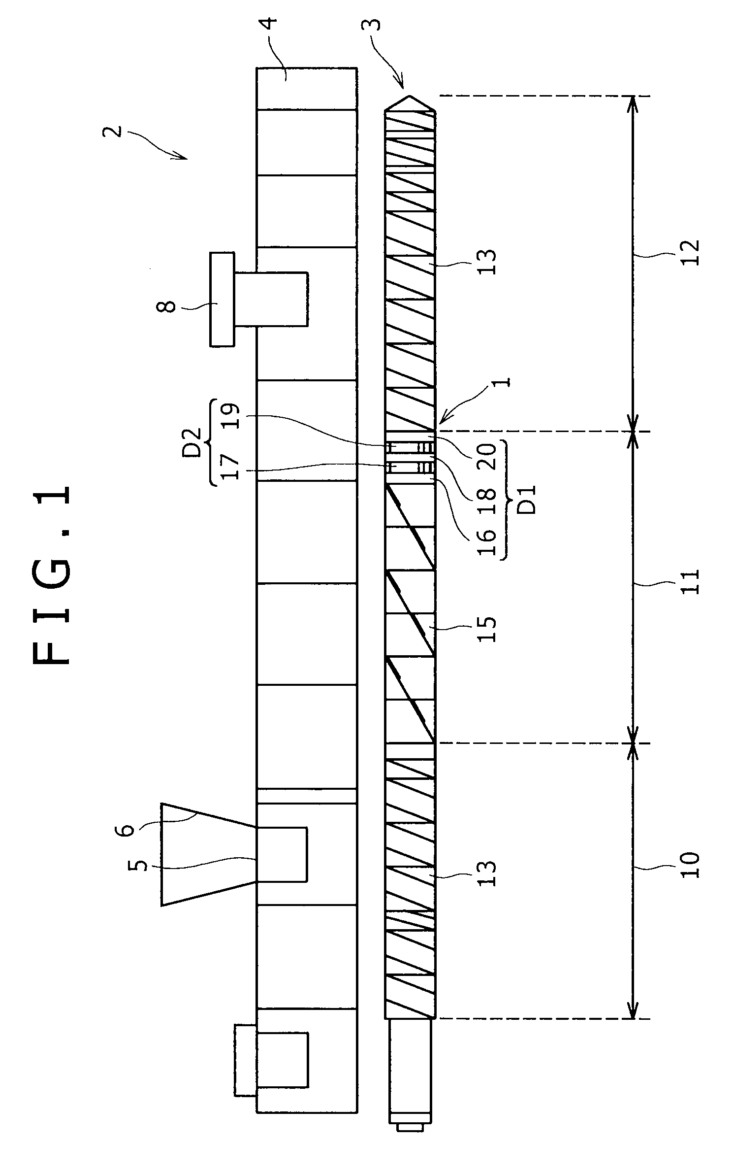
[0027]As shown in a schematic diagram of FIG. 1, the kneading disc segment 1 of the first embodiment is mounted on kneading screws 3 of a co-rotating intermeshed twin-screw extruder 2 (hereinafter referred to simply as the extruder 2 as the case may be). The twin-screw extruder 2 includes a hollow barrel 4 and kneading screws 3 inserted axially into the interior of the barrel 4. In the extruder 2, therefore, when a material is supplied into the barrel 4 and the kneading screws 3 are rotated, the material present within the barrel 4 is kneaded and is fed to a downstream side.

[0028]In connection with the following description of the extruder 2 it is assumed that the left side on the paper surface of FIG. 1 is an upstream side and the right side thereof is a downstream side, that the right-left direction on the paper surface of FIG. 1 is an axial direction and that the direction perpendicular to the axial direction is a perpendicular-to-axis direction.

[0029]The barrel 4 is formed in a ...

example

[0047]The present invention will be described below by way of a working example and a comparative example.

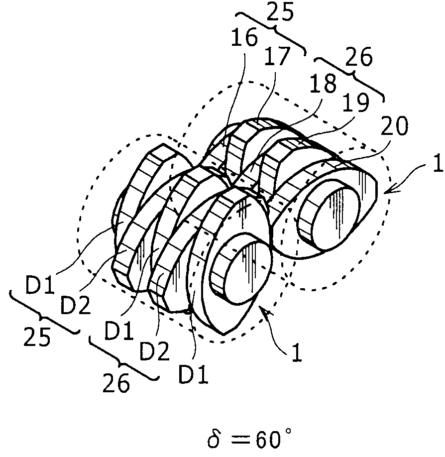
[0048]In each of the working and comparative examples, as shown in FIG. 3, the influence of the phase difference δ between the first and second kneading discs D1, D2 in the kneading disc segment 1 on the degree of kneading was calculated by computer simulation.

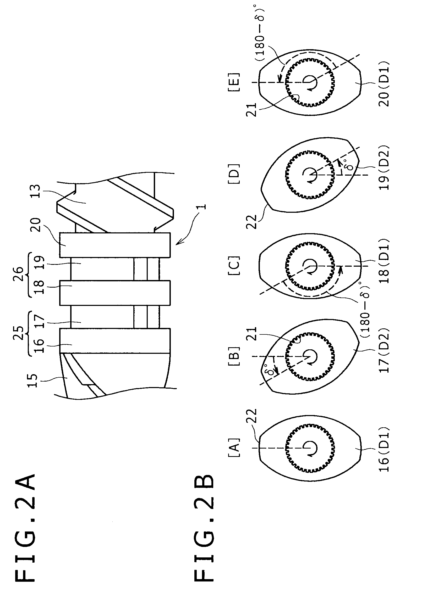
[0049]The kneading disc segment 1 used in the simulation is axially provided with a spline shaft having a diameter of 20 mm, and five kneading discs 16 to 20 are mounted continuously on the spline shaft with 5 mm spaced as an approach length from the upstream side. The five kneading discs 16 to 20 are disposed in the order of the first kneading disc D1, second kneading disc D2, first kneading disc D1, second kneading disc D2, and first kneading disc D1, from the upstream side. Each disc has a phase difference around the axis of the spline shaft and in the reverse rotational direction of the kneading screw 3. As shown in FI...


PUM

PropertyMeasurementUnit
Angleaaaaaaaaaa
Angleaaaaaaaaaa
Angleaaaaaaaaaa

Abstract

The kneading disc segment according to the present invention comprises plural disc sets each comprising two kneading discs and mounted on a kneading screw (3) which is for kneading a material while feeding the material to a downstream side. Disc sets each comprising a first kneading disc positioned on an upstream side and a second kneading disc, the second kneading disc being mounted continuously with and downstream of the first kneading disc so as to have a phase difference δ of an acute angle relative to the first kneading disc, are disposed continuously in the axial direction of the kneading screw. The first kneading discs in two continuous disc sets have a phase difference of 180°. With this construction, it is possible to attain a higher degree of kneading than in the conventional neutral kneading disc segment.

Description

BACKGROUND OF THE INVENTION[0001]1. Field of the Invention[0002]The present invention relates to a kneading disc segment and a twin-screw extruder having kneading screws each provided with the kneading disc segment.[0003]2. Description of the Related Art[0004]Generally, in a twin-screw extruder, polymeric resin pellets as matrix and a powdered additive are fed into a barrel and are fed to a downstream side while being kneaded by a pair of kneading screws inserted into the barrel, thereby a compound resin material such as a plastic compound is produced. The kneading screws are each provided with a central spline shaft and plural segments, the plural segments being fixed in a state in which the spline shaft extends therethrough, namely, fixed in a skewered state. Plural kinds of segments are known as segments constituting a kneading screw. In a kneading screw, these segments are combined axially to permit kneading suitable for predetermined use and material.[0005]Among the segments re...

Claims


Application Information

Patent Timeline
IPC IPC(8): B01F7/10B01F27/73B29C48/40B29C48/535B29C48/57B29C48/67
CPCB29B7/483B29C47/6025B29C47/6056B29B7/847B29C48/535B29C48/57B29C48/40B29B7/489B29C48/505
Inventor FUKUTANI, KAZUHISAYAMADA, SAYAKAYAMANE, YASUAKIYAMAGUCHI, KAZUO
Owner KOBE STEEL LTD
Why Eureka
Try Eureka