Head-related transfer function convolution method and head-related transfer function convolution device

a transfer function and convolution method technology, applied in the direction of stereophonic arrangments, pseudo-stereo systems, electrical devices, etc., can solve the problems of difficult to obtain an hrtf according to a desired ambient environment or room environment, and difficult to convolute an hrtf corresponding to a perceived listening environment into an audio signal

Active Publication Date: 2009-08-27
SONY CORP
View PDF13 Cites 53 Cited by
  • Summary
  • Abstract
  • Description
  • Claims
  • Application Information

AI Technical Summary

Problems solved by technology

However, in the event of convoluting HRTFs measured in an anechoic chamber as they are into audio signals, there is a problem that virtual sound image localization and orientation are somewhat fuzzy since there is no reflected waves in the case of attempting to virtually localize a sound image.
However, as described above, with the related art, measurement of HRTFs is performed with not only impulse responses of direct waves from a perceived sound source position but also accompanying impulse responses from reflected waves without being able to separate the impulse response of direct waves and reflected waves, including both, so only an HRTF according to a measured place or room is obtainable, and accordingly, it has been difficult to obtain an HRTF according to a desired ambient environment or room environment, and convolute this into an audio signal.
For example, it has been difficult to convolute an HRTF corresponding to a perceived listening environment into an audio signal such as where speakers are disposed in front on a vast plain which has neither walls nor obstructions thereabout.

Method used


Image

  • Head-related transfer function convolution method and head-related transfer function convolution device
  • Head-related transfer function convolution method and head-related transfer function convolution device
  • Head-related transfer function convolution method and head-related transfer function convolution device

Examples


Embodiment Construction

Brief Overview of Embodiment of the Present Invention

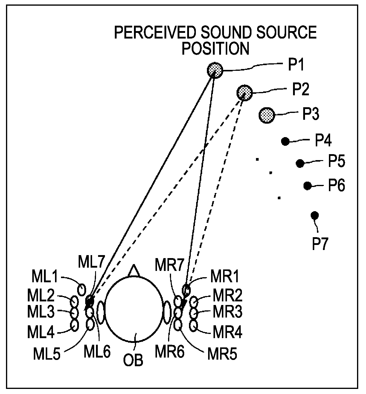
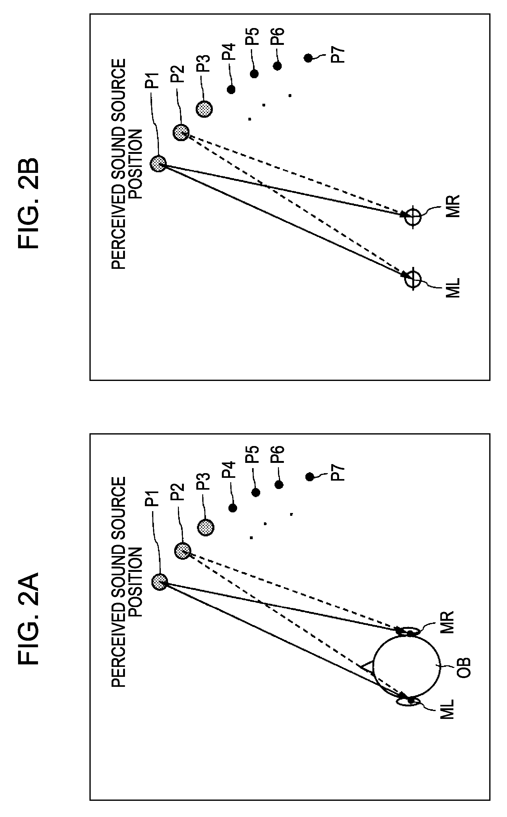
[0065]As described above, with an HRTF convolution method according to the related art, an arrangement has been made wherein a speaker is disposed in a perceived sound source position to localize a virtual sound image, an HRTF is measured assuming that an impulse response caused by a reflected wave is involved instead of an impulse response caused by a direct wave from the relevant perceived sound source position being involved (assuming that impulse responses between a direct wave and reflected wave are both included without being separated), the measured and obtained HRTF is convoluted into an audio signal without change.

[0066]That is to say, heretofore, the HRTF for a direct wave and the HRTF for a reflected wave from a sound source position perceived so as to localize a virtual sound image have been measured as an integral HRTF including both without being separated.

[0067]On the other hand, with an embodiment of the present in...


PUM


Abstract

A head-related transfer function (HRTF) convolution method arranged, when an audio signal is reproduced acoustically by an electro-acoustic conversion unit disposed in a nearby position of both ears of a listener, to convolute an HRTF into the audio signal, which allows the listener to listen to the audio signal such that a sound image is localized in a perceived virtual sound image localization position, the method including the steps of: measuring, when a sound source is disposed in the virtual sound image localization position, and a sound-collecting unit is disposed in the position of the electro-acoustic conversion unit, a direct-wave direction HRTF regarding the direction of a direct wave, and reflected-wave direction HRTFs regarding the directions of selected one or more reflected waves, from the sound source to the sound-collecting unit, separately beforehand; and convoluting the obtained direct-wave direction HRTF, and the reflected-wave direction HRTFs into the audio signal.

Description

CROSS REFERENCES TO RELATED APPLICATIONS[0001]The present invention contains subject matter related to Japanese Patent Application JP 2008-045597 filed in the Japanese Patent Office on Feb. 27, 2008, the entire contents of which are incorporated herein by reference.BACKGROUND OF THE INVENTION[0002]1. Field of the Invention[0003]The present invention relates to a convolution method and convolution device for convoluting into an audio signal a head-related transfer function (hereafter abbreviated to “HRTF”) for enabling a listener to hear a sound source situated in front or the like of the listener, during acoustic reproduction with an electric-acoustic unit such as an acoustic reproduction driver of headphones for example, which is disposed near the ears of the listener.[0004]2. Description of the Related Art[0005]In a case of the listener wearing the headphones on the head for example, and listening to acoustically reproduced signals with both ears, if the audio signals reproduced a...

Claims


Application Information

Patent Timeline
Patent Type & Authority Applications(United States)
IPC IPC(8): H04R5/00
CPCH04S1/005H04S7/304H04S2420/01H04S3/004H04S1/00H04S3/00H04S5/00
Inventor FUKUI, TAKAONISHIO, AYATAKA
Owner SONY CORP
Why Eureka
Try Eureka