Hole saw

Inactive Publication Date: 2009-08-27
K&W TOOLS CO LTD
View PDF13 Cites 4 Cited by
  • Summary
  • Abstract
  • Description
  • Claims
  • Application Information

AI Technical Summary

Benefits of technology

[0006]The present invention has been accomplished in view of the above-noted circumstances. It is one objective of the present invention to provide a hole saw, which can reduce vibration in use.
[0007]It is another objective of the present invention to provide a hole saw, which can be assembled and disassembled conveniently.
[0009]When the lid is located at the first position, the second coupling portions of the adapter are blocked by the block portion of the lid and coupled to the first coupling portions of the arbor such that the saw blade assembly are unrotatable relative to the arbor but drivable by a driving tool through the arbor to saw a workpiece steadily, thereby reducing vibration in sawing. When the lid is located at the second position, the second coupling portions of the adapter and the block portion of the lid are staggered such that the second coupling portions of the adapter are uncoupled from the first coupling portions of the arbor through the rotation of the saw blade assembly, thereby disassembling the saw blade assembly from the arbor conveniently.

Problems solved by technology

It is to be understood that the vibration may be generated in the saw blade assembly due to the unstable engagement of the positioning member with the positioning hole during rotation of the saw blade assembly, resulting in a deterioration of working accuracy.

Method used


Image

  • Hole saw
  • Hole saw
  • Hole saw

Examples


Embodiment Construction

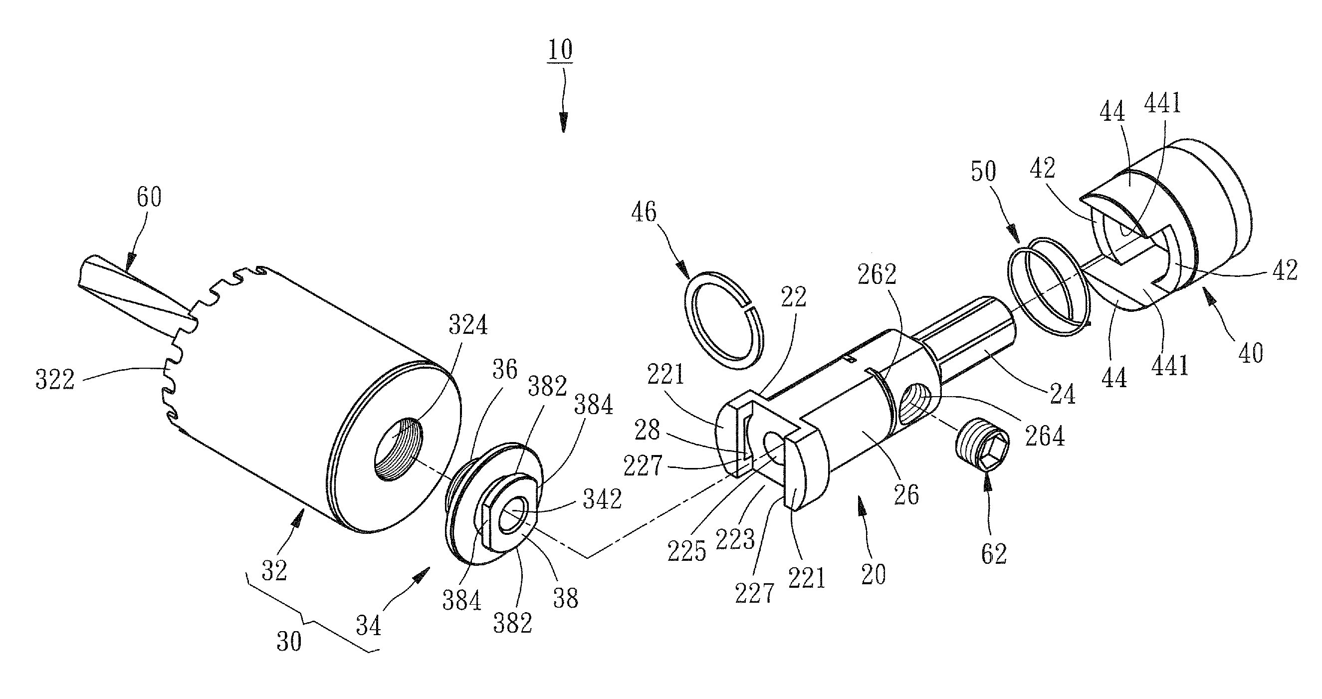
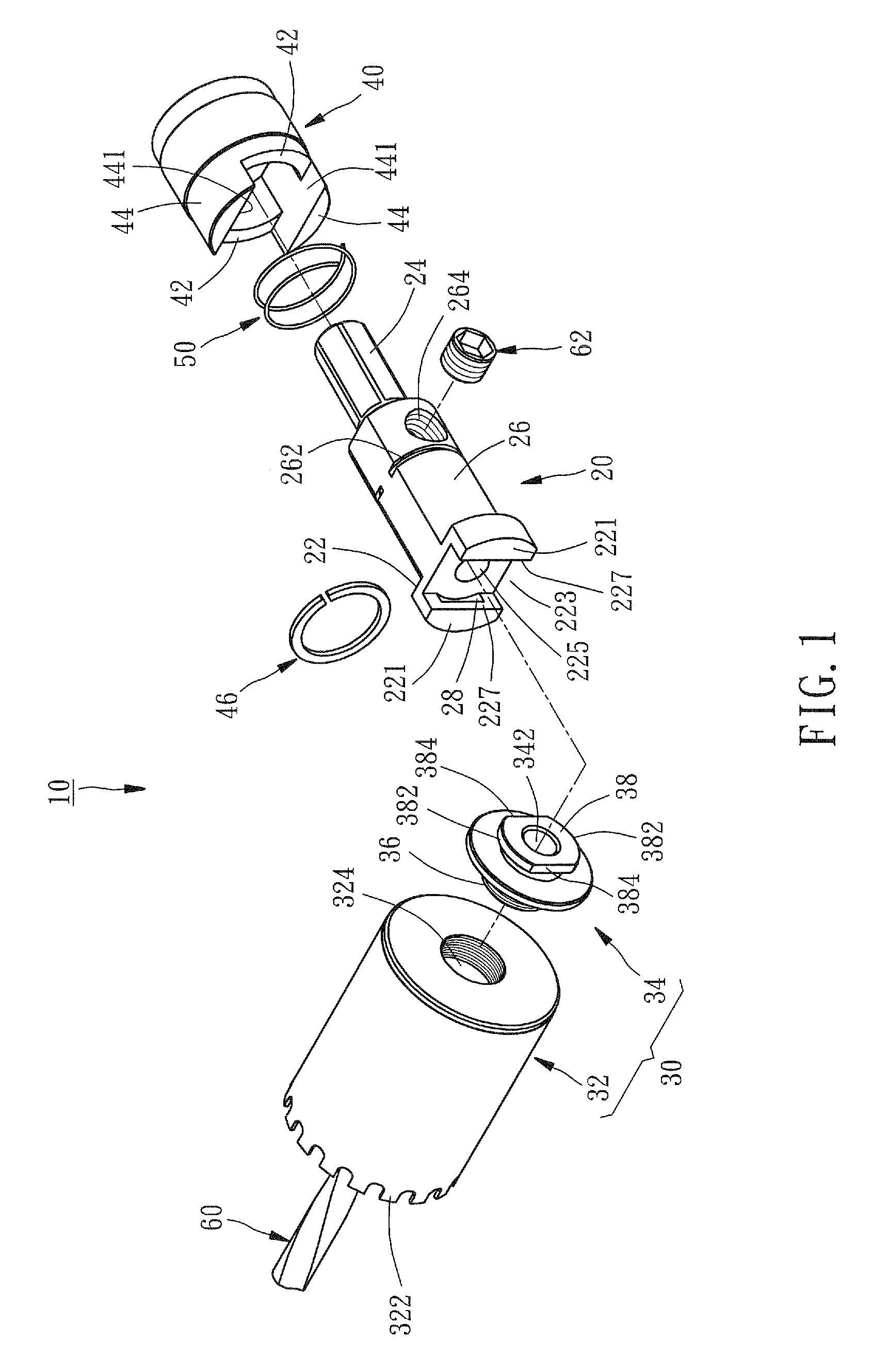
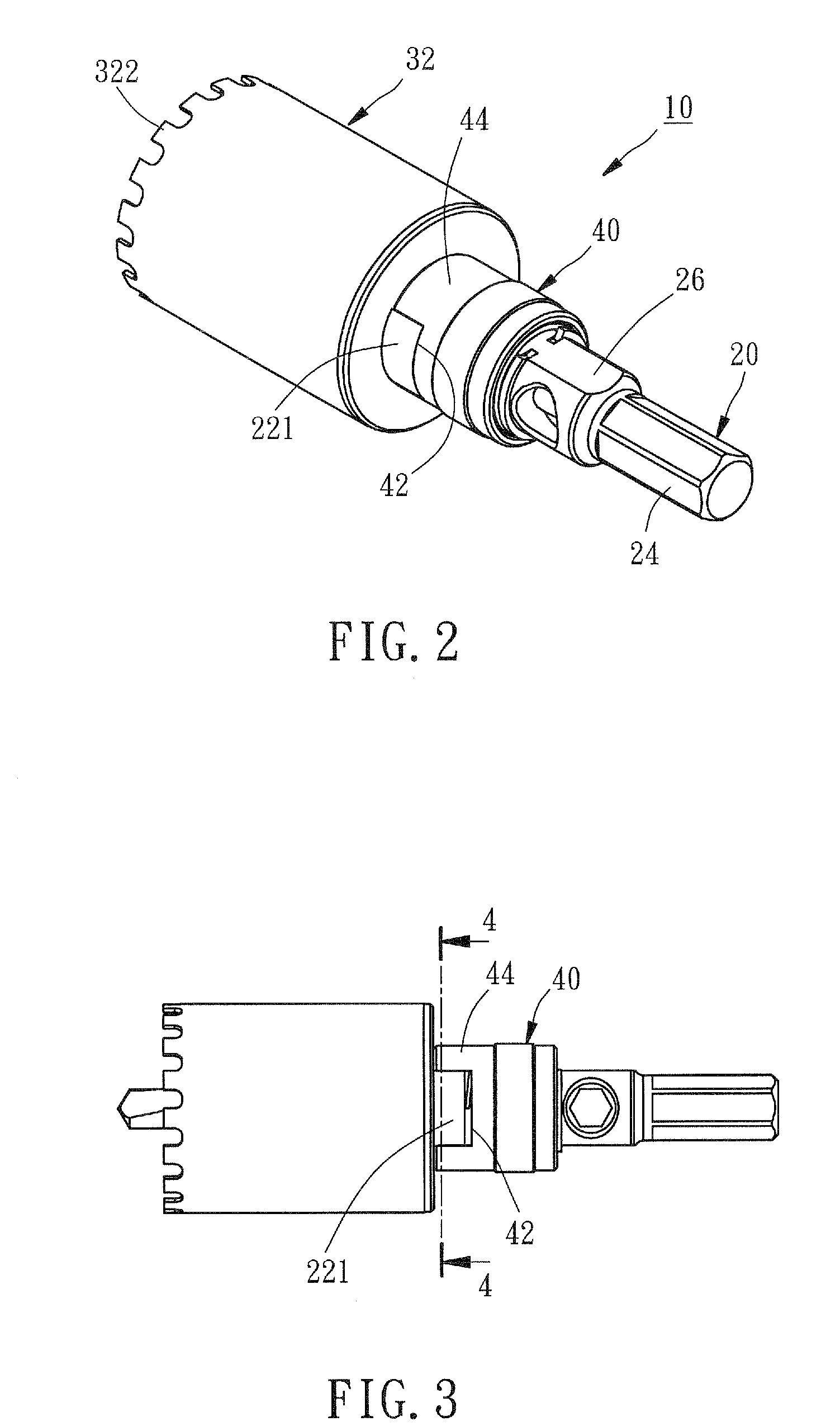
[0020]As shown in FIGS. 1 and 2, a hole saw 10 in accordance with a preferred embodiment of the present invention comprises an arbor 20, a saw blade assembly 30, a lid 40, an elastic member 50, and a drill 60.

[0021]The arbor 20 includes a coupling end 22, a transmission portion 24 capable of connecting a driving tool (not shown) such that the arbor 20 can be driven by the driving tool to rotate through the transmission portion 24, and a body portion 26 integrally connected with the coupling end 22 and the transmission portion 24 and provided with a C-shaped groove 262 and a first threaded hole 264 adjacent to the groove 262. The coupling end 22 has two opposite blocks 221, an indentation 223 located between the blocks 221, and a center hole 225 in communication with the indentation 223. The blocks 221 each have a first plane 227 to form a boundary of the indentation 223. Further, a first coupling portion 28, which is embodies as a curved depression, is recessed in each of the first ...


PUM


Abstract

A hole saw includes an arbor, a saw blade assembly having a saw blade and an adapter connected with the saw blade and provided with a protrusion received in an indentation of the arbor, a lid movably mounted on a body portion of the arbor and movable relative to the arbor between a first position where second coupling portions of the adapter are blocked by a block portion of the lid and coupled to first coupling portions of the arbor such that the saw blade assembly can't be rotatable relative to the arbor, and a second position where the second coupling portions of the adapter are staggered with the block portion and uncoupled from the first coupling portions of the arbor through the rotation of the saw blade assembly. Thus, the hole saw has the advantages of reducing vibration in use and convenience in assembly and disassembly works.

Description

BACKGROUND OF THE INVENTION[0001]1. Field of the Invention[0002]The present invention relates generally to a hole saw, and more specifically to a hole saw that can reduce vibration in use.[0003]2. Description of the Related Art[0004]A conventional hole saw mainly includes an arbor and a saw blade assembly connected with the arbor. The arbor can be driven by a driving device to drive the saw blade assembly to rotate, thereby sawing a circular hole in wood or metal.[0005]However, the arbor and the saw blade assembly are connected with each other by means of an engagement of a positioning member, such as a steel ball, with a positioning hole. It is to be understood that the vibration may be generated in the saw blade assembly due to the unstable engagement of the positioning member with the positioning hole during rotation of the saw blade assembly, resulting in a deterioration of working accuracy.SUMMARY OF THE INVENTION[0006]The present invention has been accomplished in view of the ...

Claims


Application Information

Patent Timeline
IPC IPC(8): B27B5/12
CPCB23B51/0473Y10T408/9098Y10T408/895Y10T408/95Y10T408/885Y10T408/8957
Inventor CHAO, WALLEY
Owner K&W TOOLS CO LTD
Why Eureka
Try Eureka