Nose cone assembly

Inactive Publication Date: 2009-08-27
ROLLS ROYCE PLC
View PDF13 Cites 44 Cited by
  • Summary
  • Abstract
  • Description
  • Claims
  • Application Information

AI Technical Summary

Benefits of technology

[0008]It would therefore be desirable to provide an improved nose cone assembly

Problems solved by technology

A problem with these arrangements is that the airflow into the fan, over the nose cone, is disturbed, in particular in the region surrounding the fan hub at the root portion of the fan blades.
However, the pockets are larger than the holes and so they will affect and disturb the flow over a larger area of the nose cone.
Engine testing and analysis has shown that disturbances to the airflow over the nose cone reduce the efficiency o

Method used


Image

  • Nose cone assembly
  • Nose cone assembly
  • Nose cone assembly

Examples


Example

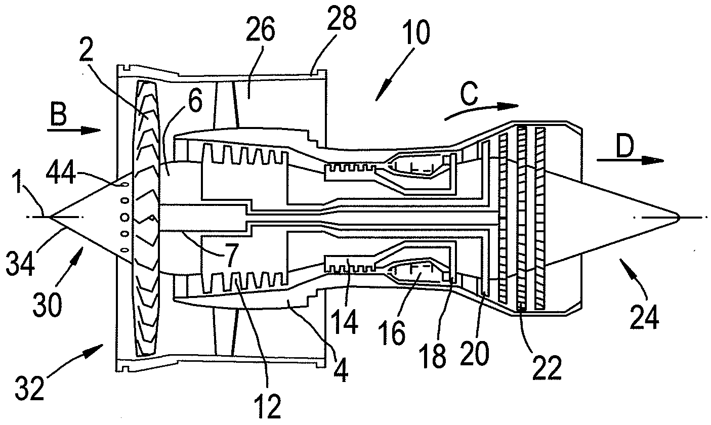
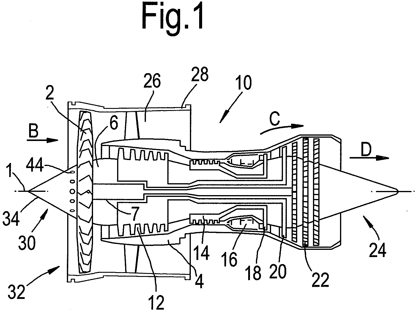
[0036]In more detail and referring to the first embodiment illustrated in FIGS. 2 and 3, the nose cone assembly 30 comprises a continuous circumferential mounting ring 38 which includes a plurality of circumferentially spaced axially extending apertures 40. The mounting ring 38 is attached to a fan hub flange 44 using axially extending bolts 42 which pass through the apertures 40 in the mounting ring 38 and through corresponding circumferentially spaced and axially extending apertures 46 in the fan hub flange 44.

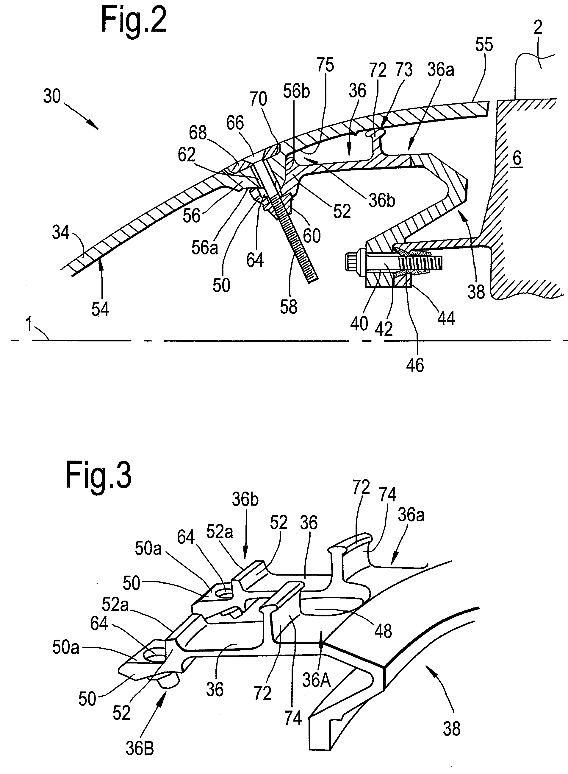
[0037]The mounting members 36 are integral with the mounting ring 38 and, in the embodiment of FIGS. 2 and 3, may be formed by machining axial slots 48 into a circumferential turned surface of the mounting ring 38 after it has been turned to provide the required geometry.

[0038]Each mounting member 36 is generally elongate and substantially parallel to the engine axis 1. Each mounting member 36 includes first and second ends 36a, 36b. Movement of the first end 36a of each mou...

Example

[0046]FIGS. 4 to 6 illustrate a second embodiment of a nose cone assembly 130 according to the invention. The nose cone assembly 130 shares many features in common with the nose cone assembly 30 of FIGS. 2 and 3, and corresponding features are therefore designated with the same reference numerals, prefixed by the number ‘1’.

[0047]The nose cone assembly 130 of FIGS. 4 to 6 differs from the nose cone assembly 30 in that the radial locating means 172 is in the form of a continuous circumferential shoulder 76 defined by the mounting ring 138. The circumferential shoulder 76 abuts a circumferential radially inwardly extending projection 78 on the inner surface 154 of the spinner 134 and acts in the same manner as the spigots 74 described with reference to FIGS. 2 and 3 to provide further radial location of the spinner 134 relative to the mounting members 136 and, hence, the fan hub 6.

[0048]Referring to FIG. 6, a resilient ‘O’ ring 77 may be located in an annular groove 79 in the circumfe...


PUM


Abstract

A nose cone assembly for a gas turbine engine comprises a spinner and a plurality of circumferentially spaced mounting members for mounting the spinner on a fan hub of the gas turbine engine. Each of the mounting members is rigid in a generally axial direction and flexible in a generally radial direction.

Description

CROSS REFERENCE TO RELATED APPLICATION[0001]This application is entitled to the benefit of British Patent Application No. GB 0803366.4, filed on Feb. 26, 2008.FIELD OF THE INVENTION[0002]Embodiments of the present invention relate to a nose cone assembly, and in particular to a nose cone assembly for a gas turbine engine.[0003]A removable nose cone, sometimes called a spinner is attached to, and rotates with a fan hub in the centre of the inlet of a gas turbine engine. This nose cone provides an aerodynamic surface covering the hub hardware and directs the inlet airflow smoothly into the hub region of the gas turbine engine fan.BACKGROUND OF THE INVENTION[0004]Conventionally the nose cone is attached to the fan hub by a number of circumferentially spaced, axially extending bolts disposed around the base portion of the cone and engaging the fan hub assembly. To provide access to these bolts, for fitting or removing the nose cone, elliptical holes are provided in the nose cone. Altern...

Claims


Application Information

Patent Timeline
IPC IPC(8): F01D5/00
CPCF01D5/066F02K3/06F02C7/04
Inventor BAGNALL, ADAM MACGREGOR
Owner ROLLS ROYCE PLC
Why Eureka
Try Eureka