Fixing method for a tip winglet and reduced tip leakage blade

a tip winglet and fixing method technology, applied in the field of turbine and compressor blades, can solve the problems of blade improvement, compressor/turbine inefficiency, high centrifugal load on compressor/turbine blades, etc., and achieve the effect of reducing the tip leakag

Inactive Publication Date: 2009-08-27
ALSTOM TECH LTD
View PDF8 Cites 12 Cited by
  • Summary
  • Abstract
  • Description
  • Claims
  • Application Information

AI Technical Summary

Benefits of technology

[0008]One aspect of the present invention deals with the problem of reducing the tip leakage of compressor or turbine blades that are subject to high centrifugal forces and thermal stresses. It addresses this problem by providing a method and an apparatus that attempts to overcome the apparent deficiencies of known winglet forming methods.
[0016]Another aspect provides a turbine or compressor blade comprising a tip portion having a pressure face, and a suction face, and a winglet with an inner edge face located on the blade such that in use blade tip leakage is reduced. An exemplary blade can be characterised by having: one or more slots through one or each of the faces; one or more keys on the inner edge face of the winglet wherein the one or more keys are receivable by one or more of the slots therein; and one or more keys received in the one or more slots therein enabling engagement of the inner edge with the tip portion face, wherein the winglet is bonded to the one or each tip portion faces.
[0017]A further aspect provides that the blade is a cooled turbine blade with internal cooling and the slots are arranged so that the winglet does not disrupt internal cooling flow of the blade by arrangement of the winglet adjacent to the tip wall.

Problems solved by technology

Further, compressor / turbine blades are subject to high centrifugal loads operating typically at minimum speeds of between 3000-3600 min−1.
A known compressor / turbine inefficiency is gas leakage across a blade tip, commonly known as tip leakage, from the pressure side to the suction side of the blade.
The problem with the application of that disclosure is the acceptance that, due to the exacting engineering requirements as a result of harsh operating environments, blade improvements must be formed during the manufacture of the blades and cannot be retrofitted.
Therefore, in order to take advantage of the solutions in that patent, existing blades must be replaced at significant cost.
While it is known to modify fan blades as described in U.S. Pat. No. 7,252,478, those solutions are not applicable to compressor or turbine blades due to very different operating environments.

Method used


Image

  • Fixing method for a tip winglet and reduced tip leakage blade
  • Fixing method for a tip winglet and reduced tip leakage blade
  • Fixing method for a tip winglet and reduced tip leakage blade

Examples


Embodiment Construction

[0024]Preferred embodiments of the present invention are now described with reference to the drawings, wherein like reference numerals are used to refer to like elements throughout. In the following description, for purposes of explanation, numerous specific details are set forth in order to provide a thorough understanding of the invention. It may be evident, however, that the invention may be practiced without these specific details. In other instances, well-known structures and devices are shown in block diagram form in order to facilitate describing the invention.

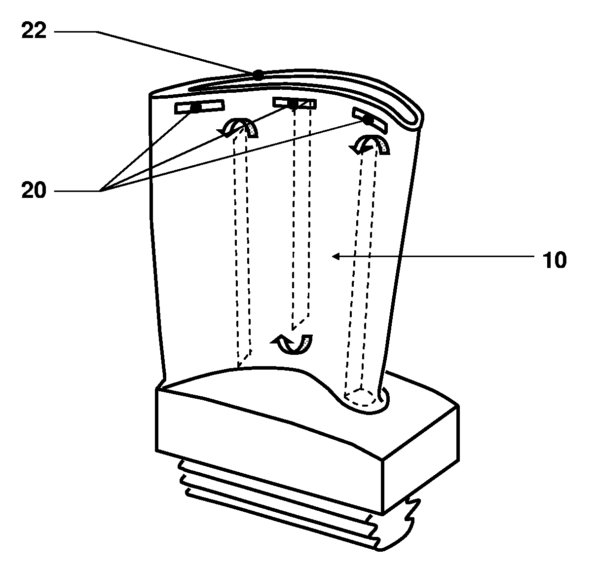
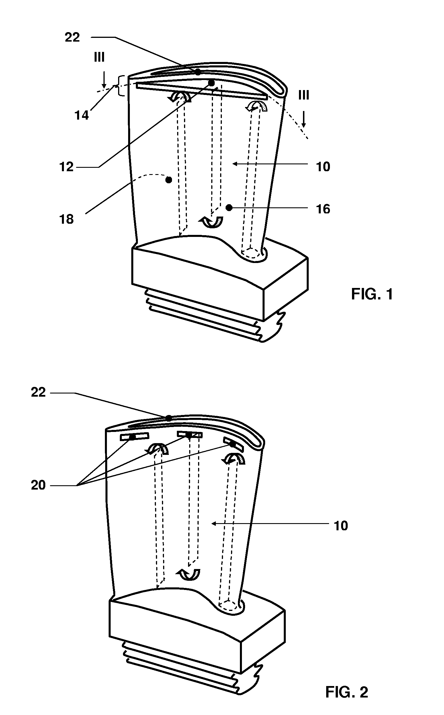
[0025]As seen in FIG. 1, disclosed is an exemplary embodiment of a manufactured compressor or turbine blade 10 that has been subsequently modified by the retrofitting of a winglet 12 on either or both of the pressure face 16 or suction face 18 of a tip portion 14. In a preferred embodiment the blade 10 is also an internally cooled turbine blade 10.

[0026]The winglet 12 is retrofitted to the compressor or turbine blade 10...


PUM

PropertyMeasurementUnit
operating temperaturesaaaaaaaaaa
temperaturesaaaaaaaaaa

Abstract

Reducing the tip leakage for an existing compressor or turbine blade (10), including internally cooled blades, can be achieved by retrofitted the blade with a tip leakage-reducing device in the form of a winglet (12). The winglet (12) can be fixed onto the tip portion by bonding the winglet onto the face or faces of the blade by a key and slot arrangement.

Description

[0001]This application claims priority under 35 U.S.C. §119 to European application no. 08101944.0, filed 25 Feb. 2008, the entirety of which is incorporated by reference herein.BACKGROUND[0002]1. Field of Endeavor[0003]The invention relates to turbine and compressor blades, more specifically to an apparatus and method for reducing the tip leakage of such blades.[0004]2. Brief Description of the Related Art[0005]Compressor and turbine blades are characterised by being subject to extreme operating conditions. These include, in the case of compressor blades, operating temperatures of typically up to 500° C. and, for turbine blades, typically above 500° C. for last stage blades, and greater than 1000° C. for first stage blades. These high temperatures can necessitate the inclusion of internal cooling. Further, compressor / turbine blades are subject to high centrifugal loads operating typically at minimum speeds of between 3000-3600 min−1. The special consideration of material selection,...

Claims


Application Information

Patent Timeline
Patent Type & Authority Applications(United States)
IPC IPC(8): F01D5/18B23P6/00
CPCB23P6/002F01D5/005F01D5/141Y10T29/49318F01D5/20F05D2230/80F05D2230/232F01D5/145
Inventor PERETI, MICHELEFERBER, JOERGEN
Owner ALSTOM TECH LTD
Why Eureka
Try Eureka