
Bumper module

a bumper module and bumper technology, applied in the direction of superstructure subunits, transportation and packaging, lighting and heating apparatus, etc., can solve the problems of relative large gaps or junctures that occur between the headlight and the bumper covering, and achieve the effect of increasing the flexibility of the bumper modul

Inactive Publication Date: 2011-02-22
PEGUFORM
View PDF16 Cites 8 Cited by
  • Summary
  • Abstract
  • Description
  • Claims
  • Application Information

AI Technical Summary

Benefits of technology

[0011]The support structure can thereby encompasses the headlight in an undercut manner, wherein this undercut area is a component of the lacquered bumper covering with the added advantage that the gap between the headlight and the bumper covering is also lacquered, thus additionally improving valuation.
[0012]The support structure can be molded unitary with the bumper covering resulting in the production-technical advantage that the bumper covering together with the support structure can be produced as one piece in one production step, wherein as the usual production method, for example, a injection molding method with thermoplastic plastics is contemplated.
[0013]However, it is also advantageous if the support structure is configured as a separate component which is firmly connected via a clip-, weld- and / or screw connection. This embodiment has the advantage that the support structure can be produced from a material different than that of the bumper covering. Thus, different plastics materials can be utilized for the bumper covering and the support structure, which can be selected also in accordance with various stability demands.
[0014]An advantageous embodiment contemplates that the support structure is produced as a separate component which includes additional webs that provide added stiffness to the support structure, in order to absorb high dynamic stress or inertia forces in heavy embodiments of the headlight.
[0015]In a further advantageous embodiment, separate support structures are provided for the two front headlights and that are produced from a relatively stable and rigid thermoplastic plastic to thus provide a firm rest to the headlight, while the bumper covering can be produced from a more flexible material wherein in the final installation of the front end module, an additional adaptation of the bumper module to the other body components can be realized. In such an embodiment, in the final installation, the headlight can be adjusted by simple guides or attachment elements to the other body components, without the need to employ additional special and expensive tolerance compensation elements in order to realize the value-increasing uniform joint course.
[0020]For that purpose, the headlight are first pre-installed together with the bumper covering and the support structures that are adjusted to the shape of the headlight as a bumper module, that subsequently can be connected with the front end support to a front end module. While it is conventional practice to date that the headlight is first connected to the front end support and adjusted with the aid of an expensive headlight adjustment device, with the method of the present invention a pre-adjustment is now superfluous. The headlights can be next fitted into the trough-shaped support structure without extensive effort by means of guidance and tolerance elements and with an optimal joint course. The bumper module resulting therefrom is according to the invention flexible enough that the adaptation to the remaining body assembly parts, such as, for example the hood and fender can be realized by simple attachment-and guidance elements. The flexibility of the bumper module is increased such that in a preferred embodiment of the present development, the support structures for each of the front headlights are arranged separately without any stiffening cross connections between the support structures.

Problems solved by technology

As a result, relatively large gaps or junctures necessarily ensue between the headlight and the bumper covering.

Method used


Image

  • Bumper module
  • Bumper module
  • Bumper module

Examples


Embodiment Construction

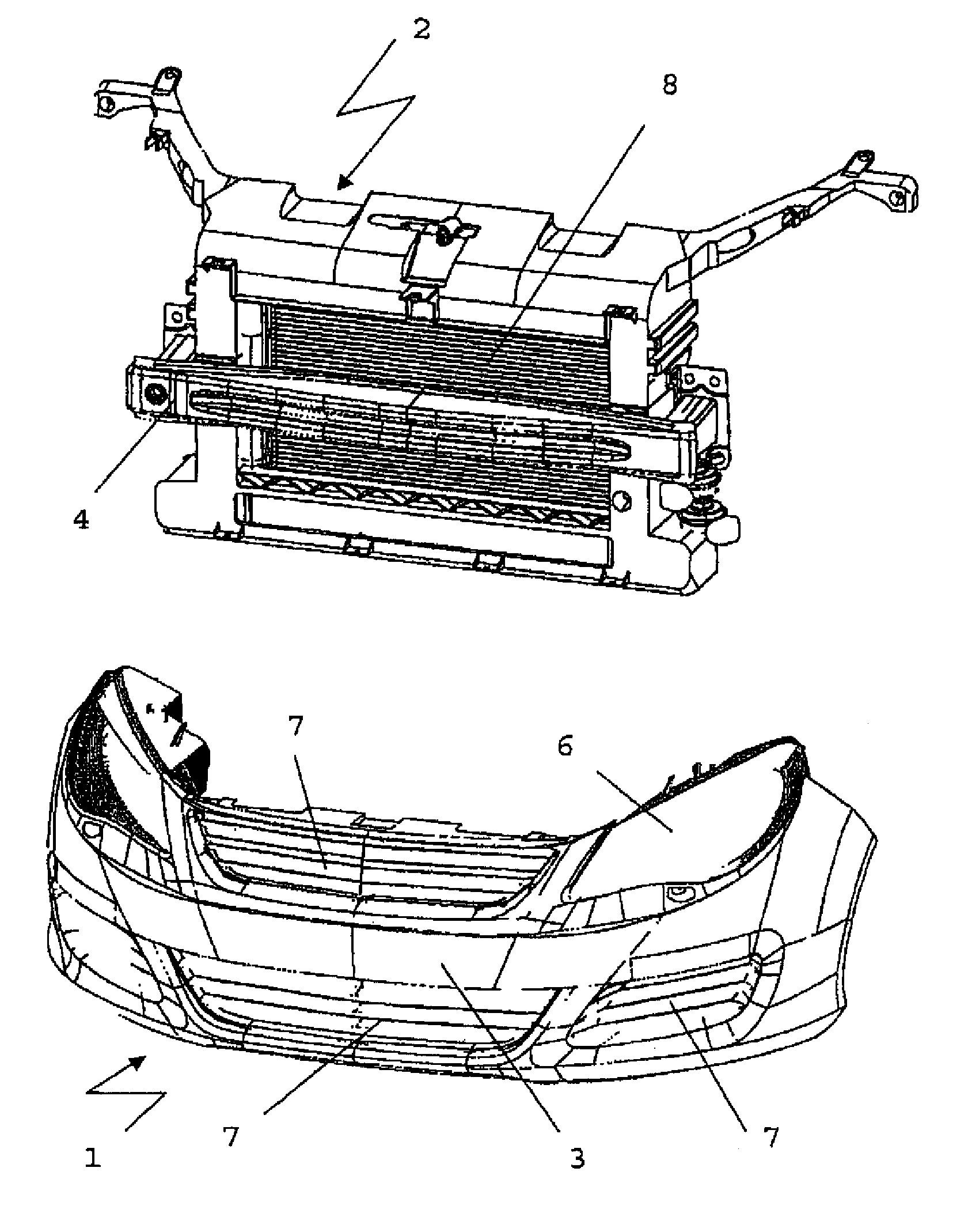
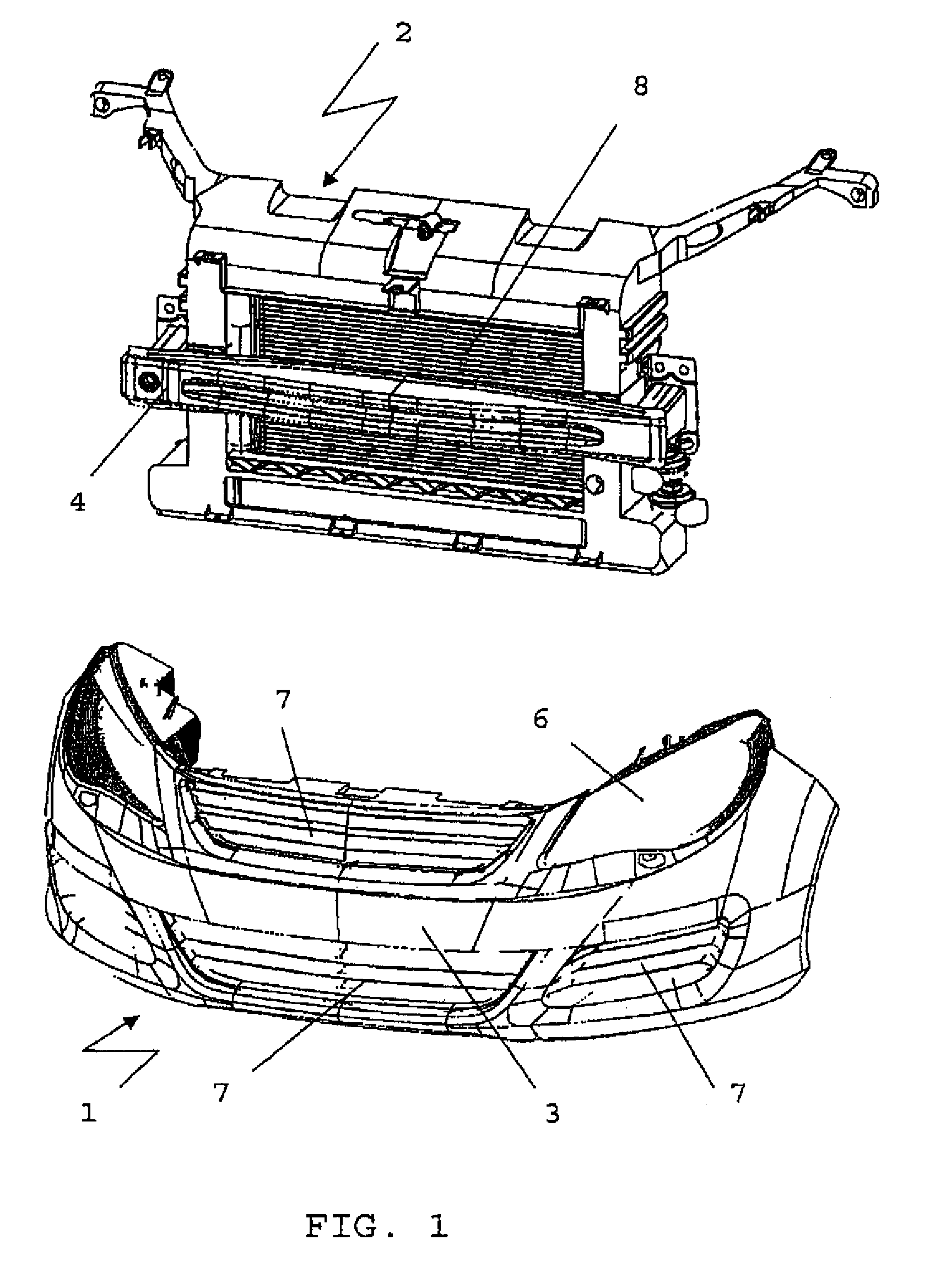
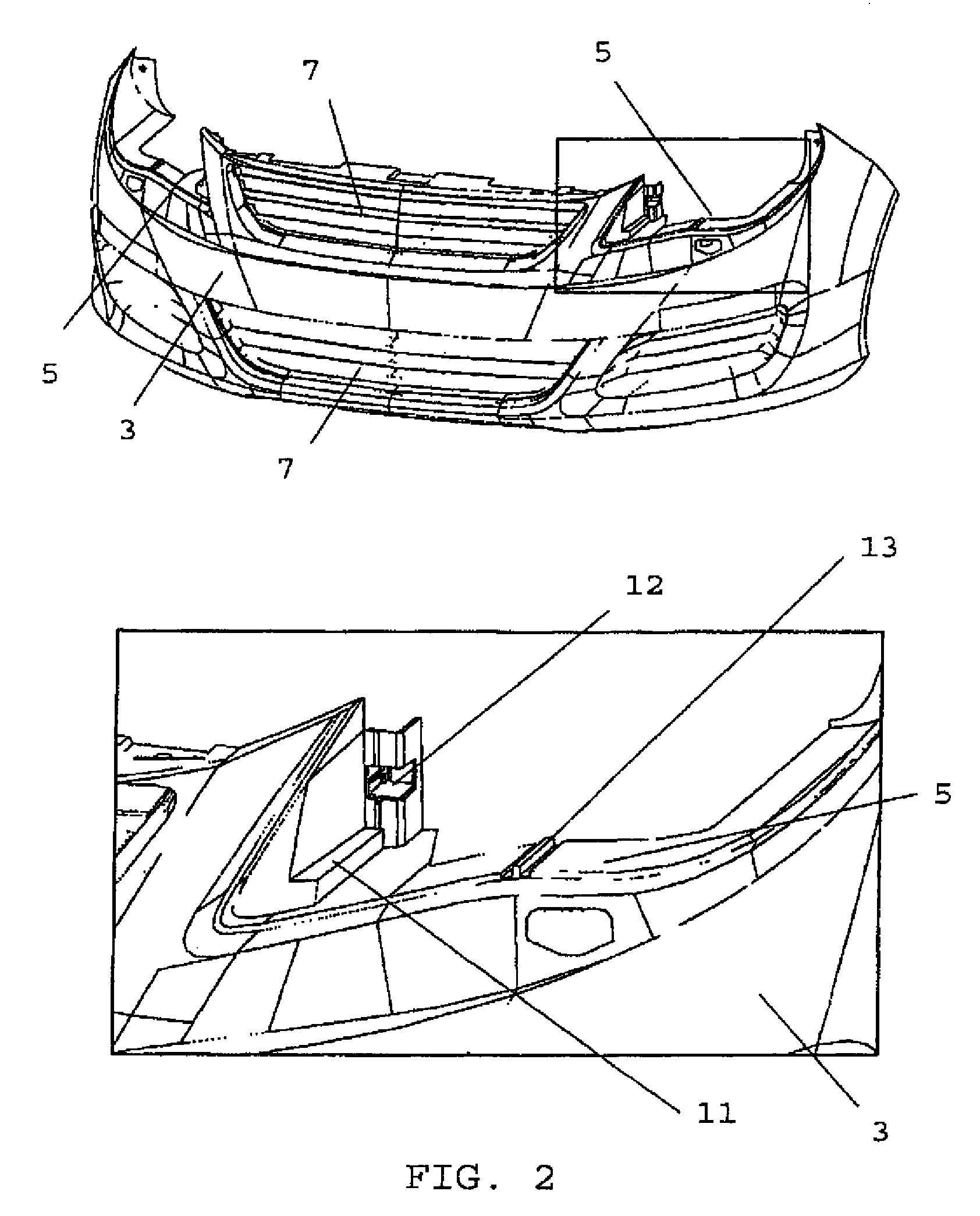
[0029]FIG. 1 shows the bumper module 1 according to the invention, which essentially consists of a bumper covering 3 showing integrated support structures 5 which, in this illustration are hidden by the front headlights 6, which are mounted in the support structures 5 with a uniform joint course.

[0030]Additional assembly elements are various radiator grill structures 7 that are integrated into the bumper covering 3. Furthermore, FIG. 1 shows separately drawn a front end support 2 with bumper-bending beam 4 and radiator 8. This subassembly can be combined with the bumper module 1 in the embodiment as shown in FIG. 1 directly into a front end module and connected, for example via corresponding support surfaces, form-fitting connections or screw connections, into a structural unit.

[0031]In a further embodiment, the subassembly consisting of a front end support 2, bumper-bending beam 4 and radiator 5 is first mounted at the vehicle and subsequently the pre-mounted bumper module, consist...


PUM

PropertyMeasurementUnit
Shapeaaaaaaaaaa

Abstract

The present invention relates to a bumper module 1 having an integrated support structure for headlight 6, by means of which the installation of headlight 6 with a visually satisfactory profile in the front region of the motor vehicle is facilitated.

Description

BACKGROUND OF THE INVENTION[0001]The present invention refers to a bumper module according to the preamble of claim 1 and a method of producing a bumper module.[0002]Usually headlight arrangements for motor vehicles are oriented and attached corresponding to their theoretically exact position at the front end support. The orientation of the headlight is carried out in a headlight adjustment facility during the pre-assembly of the front end module. Due to large deviations of the adjoining body construction components, such as for example the longitudinal beam, hood or fender, oftentimes an extensive post-adjustment of the headlights is required in order to realize the required orientation of the courses of gaps and joints. For this purpose, besides expensive headlight adjustment facilities, likewise expensive tolerance adjustment facilities are additionally utilized for final adjustment. Thus, the adjustment of the headlights is overall a relatively expensive step regarding cost and ...

Claims


Application Information

Patent Timeline
IPC IPC(8): B60Q1/00
CPCB60Q1/0416B60R19/24B60R19/50B62D65/16B62D25/084Y10T29/49826Y10T29/49876
Inventor BREISACHER, MICHAEL
Owner PEGUFORM
Learn More