
Apparatus for checking diametral dimensions of a rotating cylindrical part during a grinding thereof

a technology of rotating cylindrical parts and apparatuses, which is applied in the direction of mechanical means, instruments, manufacturing tools, etc., can solve the problems of apparatuses and their applications in grinding machines, subject to inconvenience, and the impossibility of displacement, so as to facilitate the checking of the diameter of crankpins, avoid interference, and prevent collisions

Inactive Publication Date: 2010-01-07
MARPOSS SPA
View PDF99 Cites 8 Cited by
  • Summary
  • Abstract
  • Description
  • Claims
  • Application Information

AI Technical Summary

Benefits of technology

The present invention provides an apparatus for checking crankpins rotating with an orbital motion during grinding operations. The apparatus has a high metrological performance, reliability, and small forces of inertia. It includes a measuring apparatus with a reference device that can be easily guided and controlled to check the crankpin's diameter and position during the grinding process. The apparatus is cost-effective and easy to install, and it can be used with different crankshafts and grinding machines. It also includes safety devices to prevent collisions and unwanted movements. Overall, the apparatus allows for efficient and accurate checking of crankpins during grinding operations.

Problems solved by technology

The apparatus and its applications in a grinding machine, described in the formerly mentioned patent, are subject to some inconveniences like considerable layout dimensions, in particular in a transversal direction, high forces of inertia, the impossibility of displacing in an automatic way the reference device from the rest position to the measuring position while the piece (crankshaft) is rotating.
These inconveniences are due to both the structure of the apparatus and its application in the machine.
This machine and its associated checking devices are not suitable for checking during the machining operation, among other things owing to the fact that the guide and reference devices describe trajectories that essentially correspond to the orbital motion of the associated crankpin, the speed of the orbital motion is considerably lower with respect to that occurring in the course of the machining in a crankpin grinding machine and the displacement of the checking devices from a rest position to an operating condition occurs when the crankshaft is not rotating.
The grinding machine cannot machine workpieces rotating with an orbital motion, nor is the measuring apparatus suitable for a similar type of application.

Method used


Image

  • Apparatus for checking diametral dimensions of a rotating cylindrical part during a grinding thereof
  • Apparatus for checking diametral dimensions of a rotating cylindrical part during a grinding thereof
  • Apparatus for checking diametral dimensions of a rotating cylindrical part during a grinding thereof

Examples


Embodiment Construction

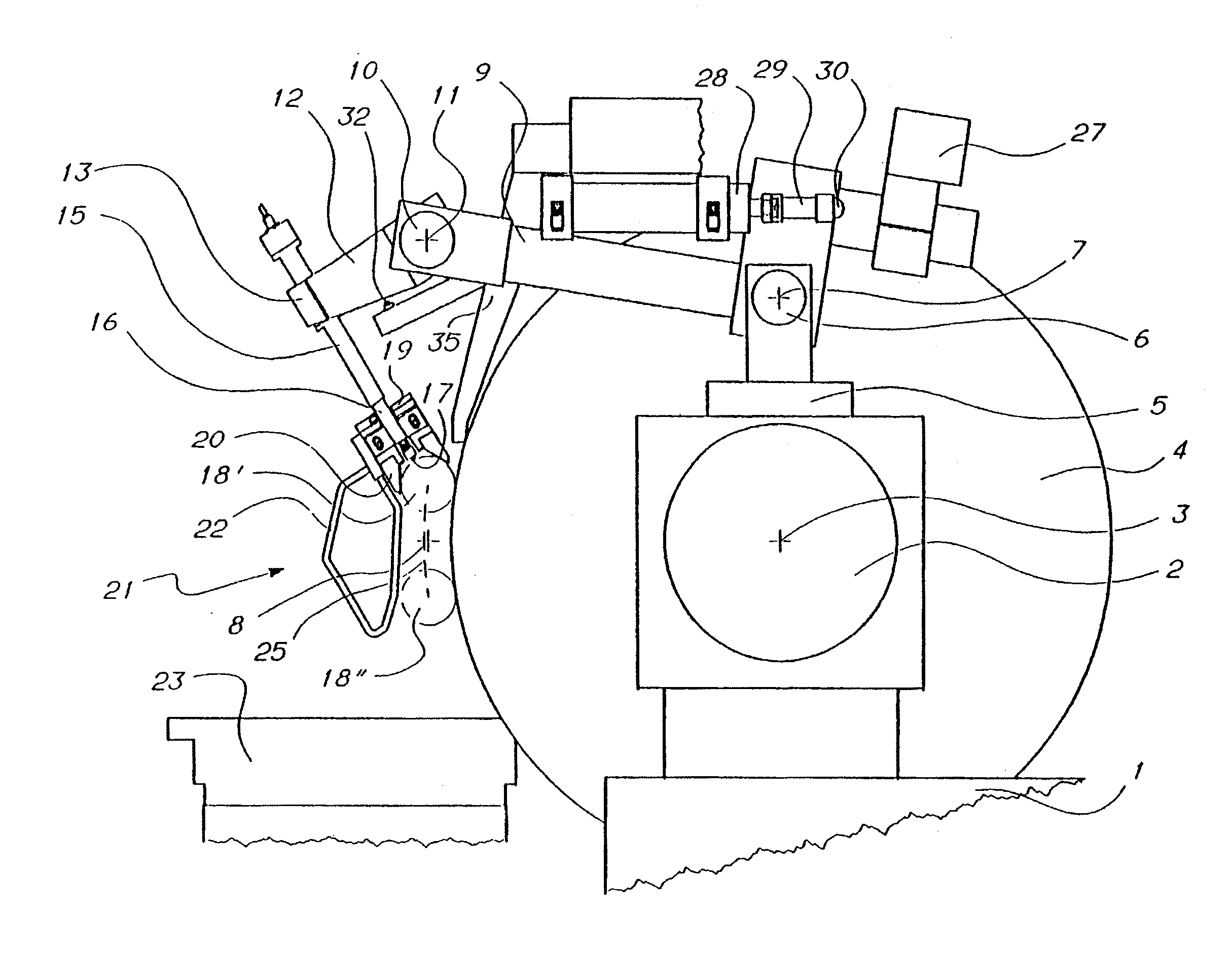
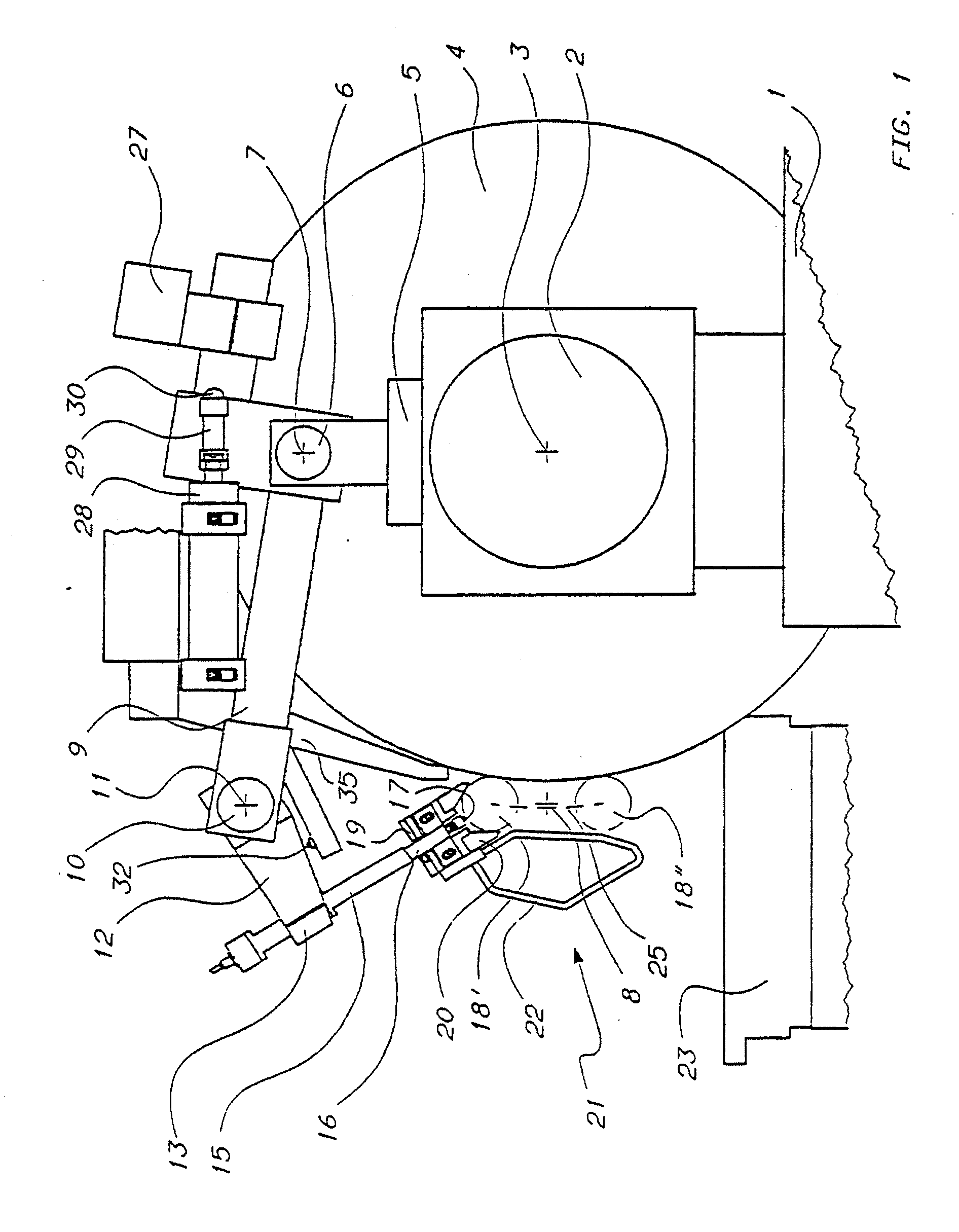
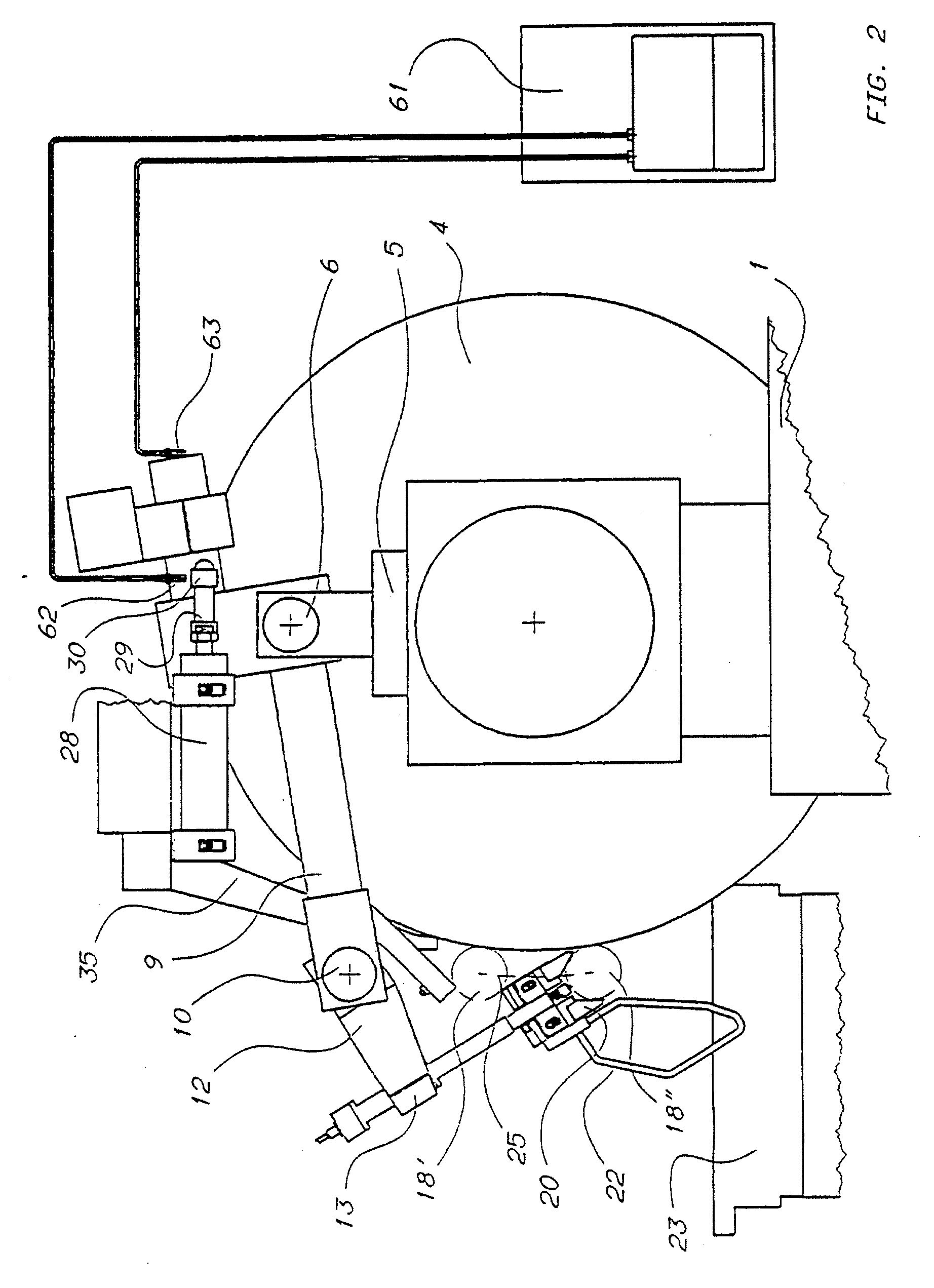
[0024]With reference to FIG. 1, the grinding-wheel slide 1 of a computer numerical control (“CNC”) grinding machine for grinding crankshafts supports a spindle 2 that defines the axis of rotation 3 of grinding wheel 4. Above spindle 2 the grinding-wheel slide 1 carries a support device including a support element 5 that, by means of a rotation pin 6, with preloaded bearings—not shown—, defining a first axis of rotation 7 parallel to the axis of rotation 3 of grinding wheel 4 and to the axis of rotation 8 of the crankshaft, supports a first rotating, coupling, element 9. The axis of rotation 7 substantially lies in a vertical plane wherein the axis of rotation 3 of grinding wheel 4 lies, above the axis of rotation 3 of grinding wheel 4 and below the upper periphery of the grinding wheel. In turn, coupling element 9, by means of a rotation pin 10, with preloaded bearings—not shown—, defining a second axis of rotation 11 parallel to the axis of rotation 3 of grinding wheel 4 and to the...


PUM


Abstract

An apparatus for checking the diameter of crankpins (18) of a crankshaft (34) in the course of the machining in a grinding machine comprises a first arm (9) rotating with respect to a support (5) arranged on the grinding-wheel slide (1) of the grinding machine, a second arm (12) rotating with respect to the first, a reference device (20) carried by the second arm and a measuring device (16, 17, 40-45) associated with a reference device. A guide device (21), fixed to the reference device (20), enables the apparatus to engage a crankpin, in the course of the orbital motion of the crankpin, and limit the displacements of the first arm and those of the second arm when a control device (28-30) displaces the apparatus to a rest position.

Description

TECHNICAL FIELD[0001]The present invention relates to an apparatus for checking the diameter of crankpins rotating with an orbital motion about a geometrical axis, in the course of the machining in a numerical control grinding machine including a worktable, defining said geometrical axis, and a grinding-wheel slide with a reference device for cooperating with the crankpin to be checked, a measuring device, movable with the reference device, and a support device for supporting the reference device and the measuring device, the support device having a support element, a first coupling element coupled to the support element so as to rotate about a first axis of rotation parallel to said geometrical axis, and a second coupling element carrying the reference device and coupled, in a movable way, to the first coupling element.BACKGROUND ART[0002]U.S. Pat. No. 4,637,144 discloses an apparatus for checking the diameter of crankpins orbiting about a geometrical axis, in the course of the mac...

Claims


Application Information

Patent Timeline
Patent Type & Authority Applications(United States)
IPC IPC(8): G01B3/00B23Q17/20B24B5/42B24B49/04
CPCB24B49/04B24B5/42
Inventor DALL'AGLIO, CARLOCIPRIANI, RICCARDO
Owner MARPOSS SPA
Learn More