Double-waist-wheel gas flowmeter

A technology of gas flowmeter and waist wheel, which is applied in the direction of liquid/fluid solid measurement, volume measurement, measuring device, etc. It can solve the problem that the bearing cannot be cleaned and lubricated well, the stability of the flowmeter is affected, and the measurement performance of the small flow is shortened. and other problems, to achieve the effect of compact structure, small space occupation and simple structure

Active Publication Date: 2022-07-29
浙江磐博科技有限公司
View PDF10 Cites 1 Cited by
  • Summary
  • Abstract
  • Description
  • Claims
  • Application Information

AI Technical Summary

Problems solved by technology

[0003] The metering chamber of a pair of rotor flowmeters currently on the market is mostly composed of a housing and front and rear end plates. When the gas passes through the rotor assembly of the flowmeter, a volumetric flowmeter will be generated at the outlet of the gas Roots flowmeter. The unique pulsating flow leads to unbalanced displacement and large vibration in the pipeline, which affects the operation stability of the entire flowmeter, reduces the measurement accuracy of the flowmeter and shortens the service life of the product
[0004] The flowmeters with two pairs of rotors currently used in the market basically directly rotate the two pairs of rotors through the coupling, so that the bearings of the coupling cannot be cleaned and lubricated well, which affects the small flow rate of the meter. Metering performance and shortened product life

Method used


Image

  • Double-waist-wheel gas flowmeter
  • Double-waist-wheel gas flowmeter
  • Double-waist-wheel gas flowmeter

Examples


Embodiment 1

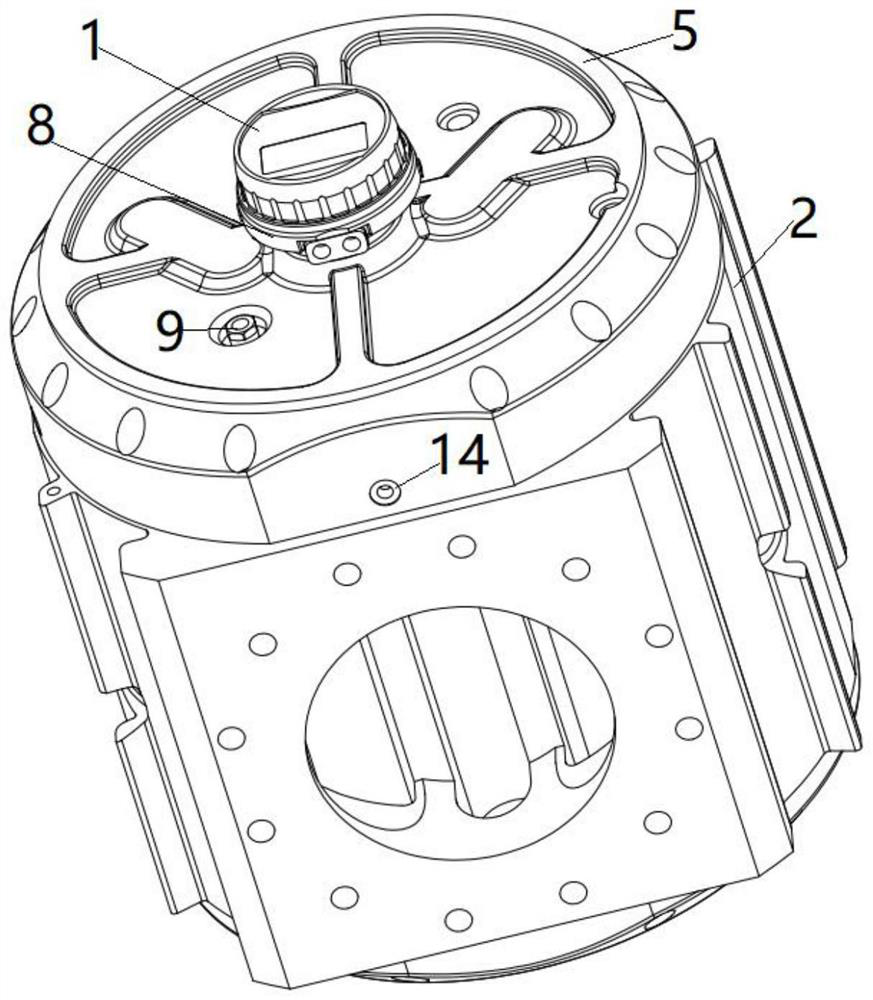
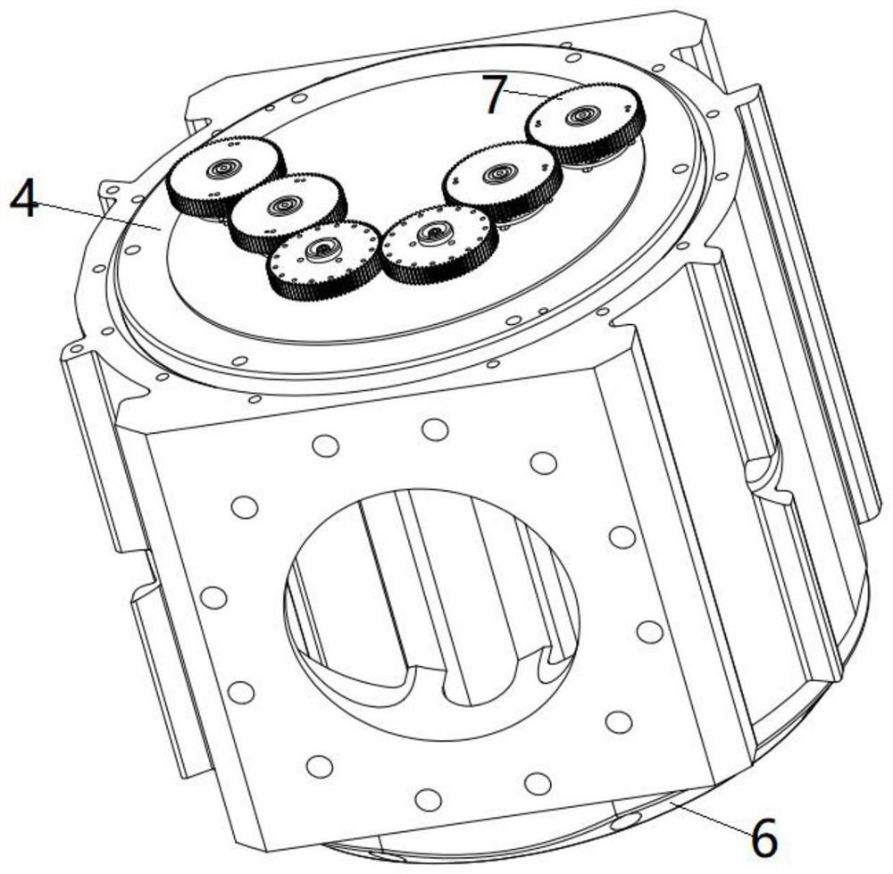
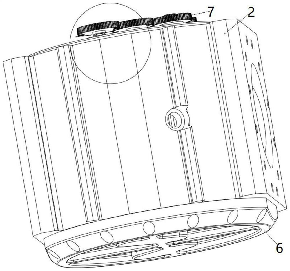
[0034] like Figure 1-8 As shown, the present invention discloses a double-waisted gas flow meter, including a counting module 1 and a metering module, the metering module includes a metering chamber shell 2, a synchronous rotor 3, a front end cover 5, a rear end cover 6, a front end plate 4, The rear end plate, the synchronous gear set 7 and the magnetic coupler 8, the synchronous rotor 3 is arranged in the measuring chamber shell 2, the synchronous rotor 3 is a figure-8 waist wheel, and the contour curve of the waist wheel is designed based on the involute meshing theory, and the synchronous rotor 3 There are two groups, two in each group. The two groups of synchronous rotors are arranged on both sides of the metering chamber shell 2, and the best matching clearance is maintained between the waist wheel, the metering chamber shell 2, the front end plate 4 and the rear end plate. , in order to ensure the non-contact sealing of the waist wheel during the rotation process, the ...


PUM


Abstract

The invention discloses a double-waist-wheel gas flow meter, and relates to the technical field of gas measurement, the double-waist-wheel gas flow meter comprises a counting module and a metering module, the metering module comprises a metering chamber shell, two groups of synchronous rotors, a front end cover, a rear end cover, a front end plate, a rear end plate, a synchronous gear set and a magnetic coupler, each group comprises two synchronous rotors, each group comprises two synchronous rotors, and each group comprises two synchronous rotors; the synchronous rotors are arranged on the two sides of the metering chamber shell respectively, rotating shafts are arranged at the two ends of the synchronous rotors, the front end plate and the rear end plate are arranged at the front end and the rear end of the metering chamber shell respectively, the rotating shafts penetrate through the front end plate and the rear end plate, and the synchronous gear set is arranged on the front end plate and fixedly connected with the rotating shafts. The front end cover and the rear end cover correspondingly cover the front end plate and the rear end plate, a magnetic coupler is arranged on the front end cover, one end of the magnetic coupler penetrates through the front end cover and is rotationally connected with the synchronous gear set, and the other end of the magnetic coupler is rotationally connected with the counting module. The device is simple and compact in structure, small in occupied space, wide in range and low in starting flow.

Description

technical field [0001] The invention belongs to the technical field of gas measurement, and in particular relates to a double-waisted gas flowmeter. Background technique [0002] Gas waist wheel flowmeter, also known as gas Roots flowmeter, is a high-precision metering instrument used for continuous or intermittent measurement of gas or liquid flow in pipelines. It has the characteristics of high precision, good reliability, light weight, long life, low operating noise, easy installation and use, etc. The waist wheel flowmeter can indicate the cumulative flow, instantaneous flow, single flow, etc. The ideal meter for flow detection. [0003] The metering cavity of a pair of rotor flowmeters currently on the market is mostly composed of a shell and front and rear plates. When the gas passes through the rotor assembly of the flowmeter, a positive displacement flowmeter will be generated at the outlet of the gas Roots flowmeter. The unique pulsating flow leads to unbalanced d...

Claims


Application Information

Patent Timeline
Patent Type & Authority Applications(China)
IPC IPC(8): G01F11/28G01F15/00G01F15/14G01F15/075
CPCG01F11/28G01F15/00G01F15/14G01F15/075
Inventor 杨国芬林念杰叶友传徐亦鹏胡奕利
Owner 浙江磐博科技有限公司
Why Eureka
Try Eureka