Internally heated nozzle adapter

a technology of nozzle adapters and nozzles, which is applied in the field of injection molding machines, can solve the problems of reducing the efficiency of heaters, affecting the operation of nozzle adapters, and difficult to extract heaters from tight cylindrical passageways,

Active Publication Date: 2009-08-27
APTIV TECH LTD
View PDF6 Cites 8 Cited by
  • Summary
  • Abstract
  • Description
  • Claims
  • Application Information

AI Technical Summary

Benefits of technology

[0007]In an exemplary embodiment of the invention, a nozzle adapter for an injection molding machine includes a body and one or more retainers mountable to an outer surface of the body. When the body and a retainer are assembled together they define a cavity adapted to contain a cartridge heater between the body and the retainer. Access to allow replacement of the cartridge heater can be gained by removing the retainer from the body without removing the entire nozzle adapter from the injection molding machine. Additionally, a cartridge heater can be replaced by accessing the nozzle adapter from a side, which typically offers an advantage over requiring access to an end of the nozzle adapter.

Problems solved by technology

The conventional method of inserting the heater into a hole requires that the hole diameter be large enough to accommodate a slip fit, which may result in reduced heater efficiency.
In the event a heater needs to be replaced, material galling or sticking may make it difficult to extract a heater from a tight cylindrical passageway.
It may be necessary to drill out a defective heater from a nozzle adapter, resulting in the potential of damaging the nozzle adapter.
For example, the process of drilling out a cartridge heater may result in enlargement of the hole, so that heat transfer between the nozzle adapter and the replacement heater is degraded.
This process is time consuming and may lead to extended machine downtime.

Method used


Image

  • Internally heated nozzle adapter
  • Internally heated nozzle adapter
  • Internally heated nozzle adapter

Examples


Embodiment Construction

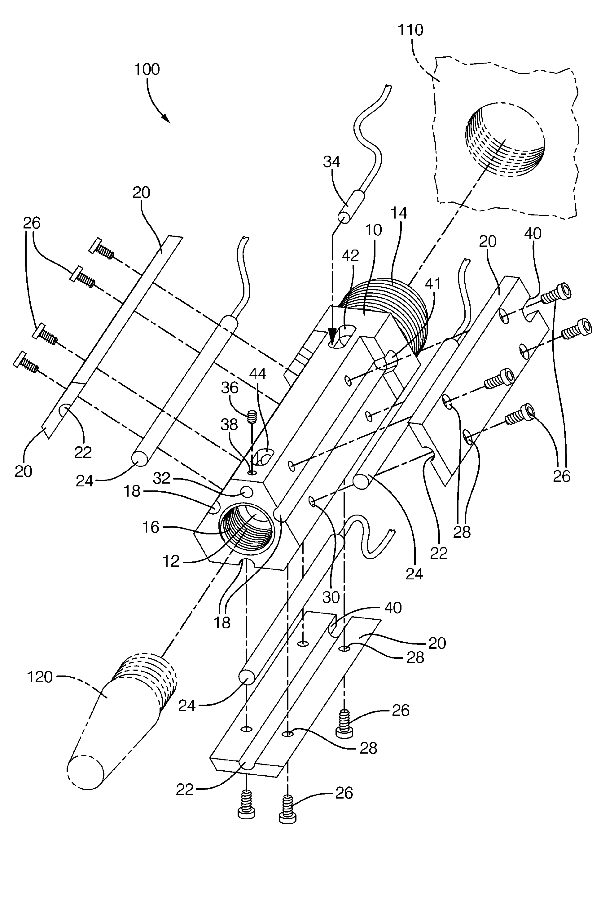
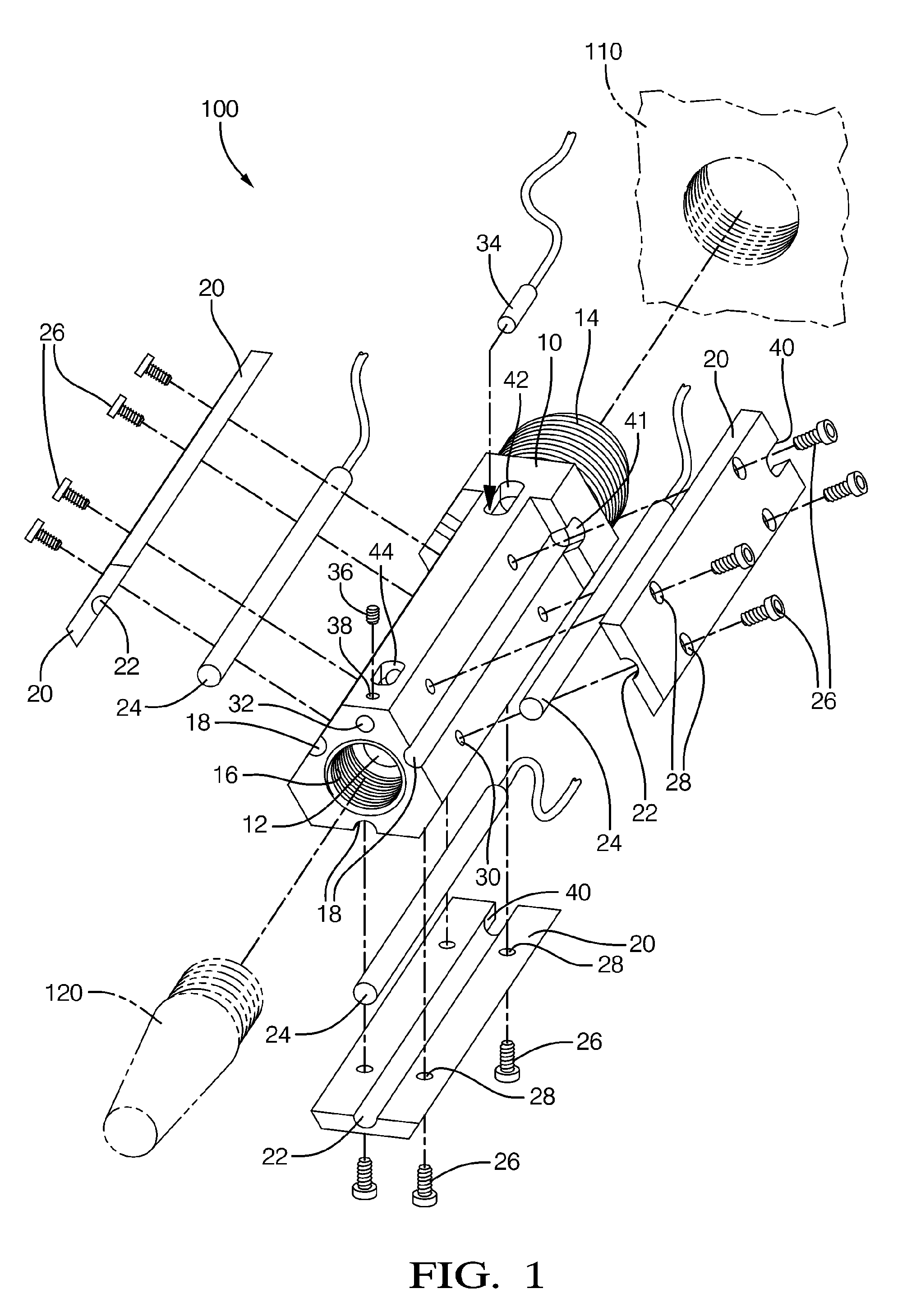
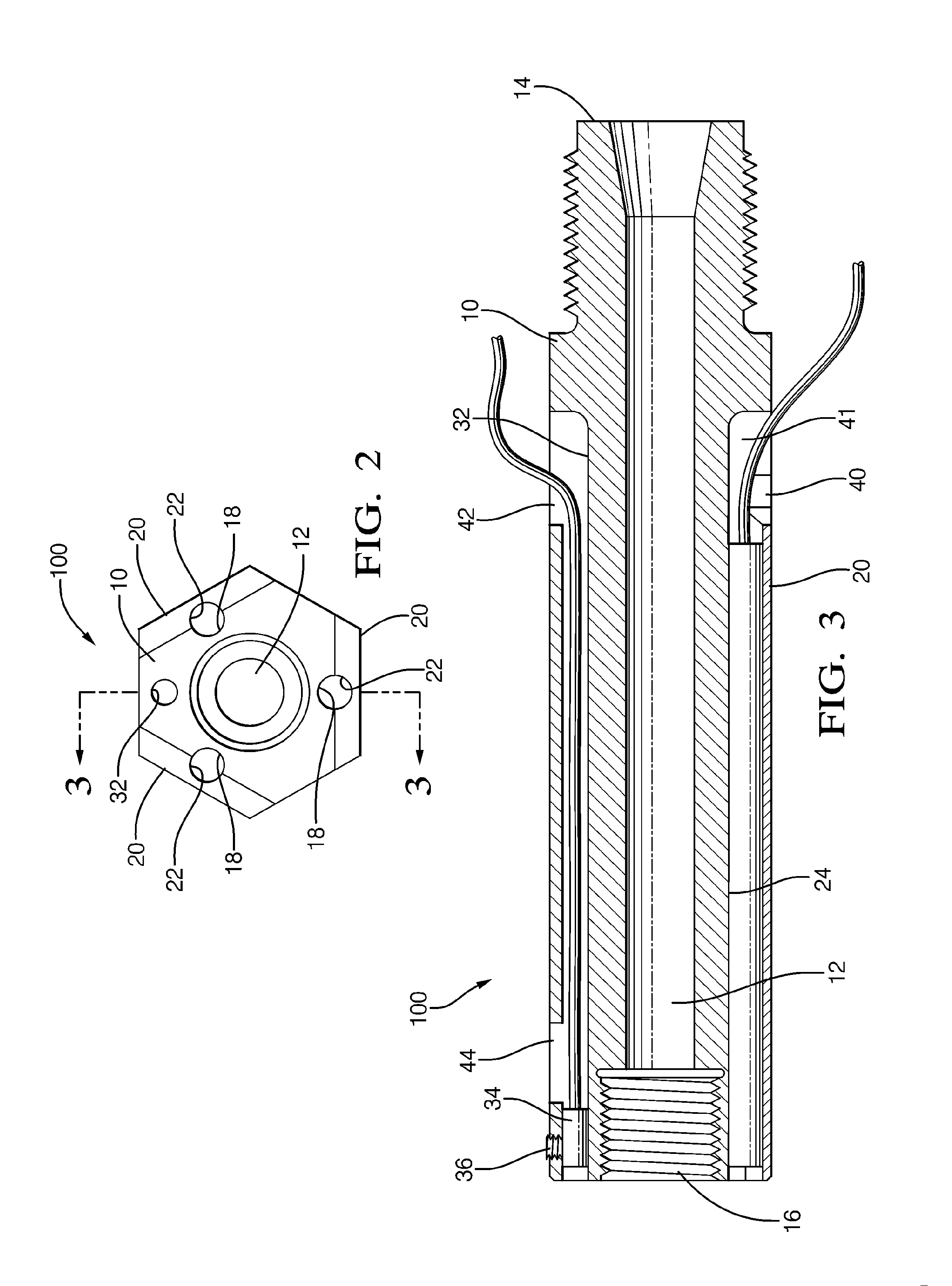
[0011]In accordance with an exemplary embodiment of the invention, FIG. 1 shows an exploded view of an internally heated nozzle adapter 100. The nozzle adapter 100 has a first end 14 adapted to mount to a molding machine 110, and a second end 16 adapted to mount to a nozzle 120 that interfaces with a mold (not shown). In the embodiment shown in FIG. 1, the nozzle adapter 100 comprises a body 10, which defines a melt passage 12 extending from the first end 14 to the second end 16. When the nozzle adapter 100 is in use, the melt passage 12 is adapted to convey melted plastic from the molding machine 110 to the nozzle 120.

[0012]In the embodiment shown in FIG. 1, the body defines a plurality of grooves on the outside surface, wherein each groove 18 is adapted to receive a cartridge heater 24. The embodiment in FIG. 1 contains three such grooves 18, to accommodate three cartridge heaters 24. The body 10 is preferably made of metal.

[0013]FIG. 1 also shows a set of heater retainers 20. Eac...


PUM

PropertyMeasurementUnit
temperatureaaaaaaaaaa
pressureaaaaaaaaaa
diameteraaaaaaaaaa

Abstract

A nozzle adapter for an injection molding machine includes a body and one or more retainers mountable to an outer surface of the body. When the body and a retainer are assembled together they cooperate to define a cavity adapted to contain a cartridge heater between the body and the retainer. Access to allow replacement of the cartridge heater can be gained by removing the retainer from the body without removing the entire nozzle adapter from the injection molding machine.

Description

CROSS-REFERENCE TO RELATED APPLICATIONS[0001]This application claims the benefit of U.S. Provisional Application No. 61 / 066,691, filed Feb. 22, 2008, which is incorporated by reference.TECHNICAL FIELD OF INVENTION[0002]This invention relates to injection molding machines, and in particular to nozzle adapters for injection molding machines.BACKGROUND OF THE INVENTION[0003]Injection molding is a process in which a molding machine forces melted plastic through a nozzle into a mold cavity where it is held until it solidifies, resulting in a solid part that assumes the shape defined by the cavity. Before injection into the mold, the plastic must be heated to a temperature which allows it to flow under pressure. Molding machines may use a nozzle adapter that defines a melt passage to convey molten plastic from the machine through the nozzle to the mold. It is important to keep the molten material at the proper temperature to optimize the flow of the material into the mold. To achieve and ...

Claims


Application Information

Patent Timeline
Patent Type & Authority Applications(United States)
IPC IPC(8): B29C45/20
CPCB29C2045/2743B29C45/2737
Inventor HOLLIDAY, CHRISTOPHER D.
Owner APTIV TECH LTD
Why Eureka
Try Eureka