
Method and apparatus for positioning a biventrivular pacemaker lead and electrode

Active Publication Date: 2009-08-27
MEDTRONIC INC
View PDF16 Cites 90 Cited by
  • Summary
  • Abstract
  • Description
  • Claims
  • Application Information

AI Technical Summary

Benefits of technology

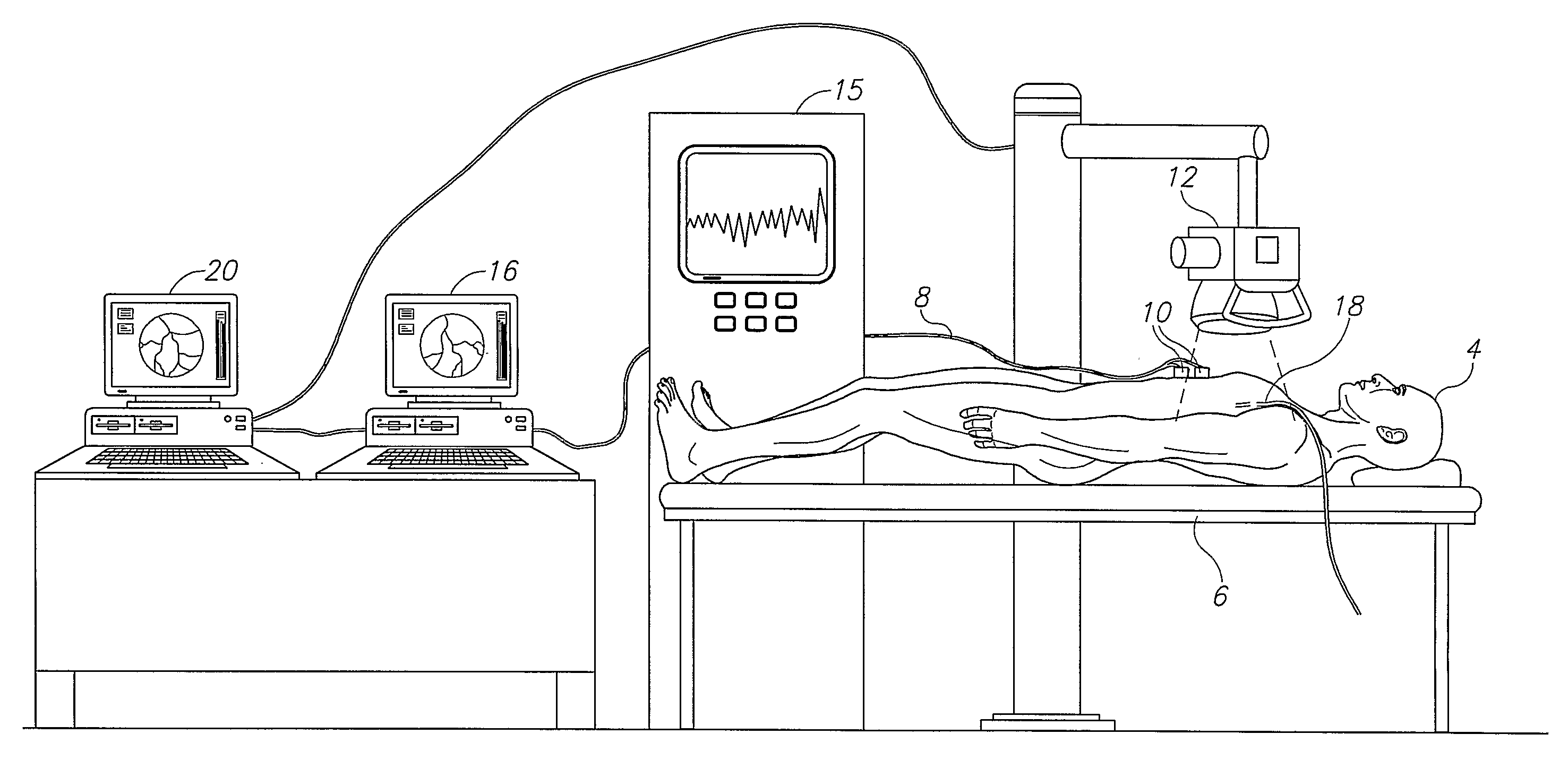
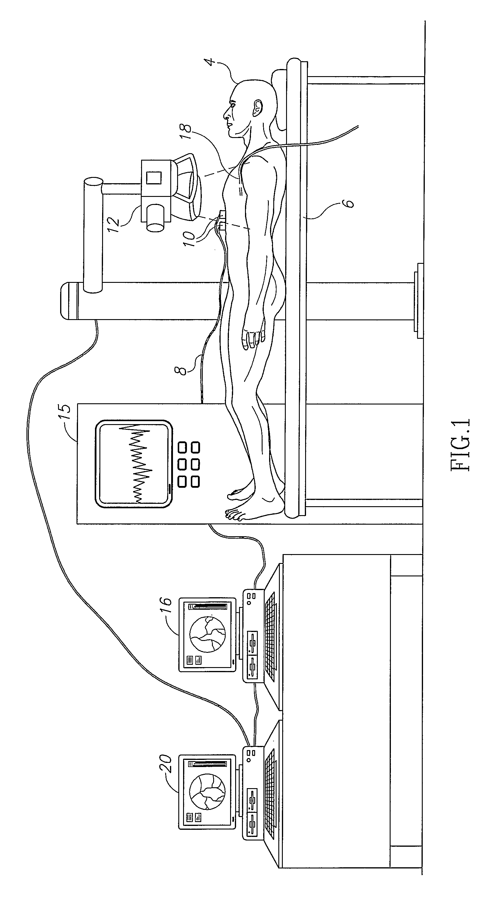
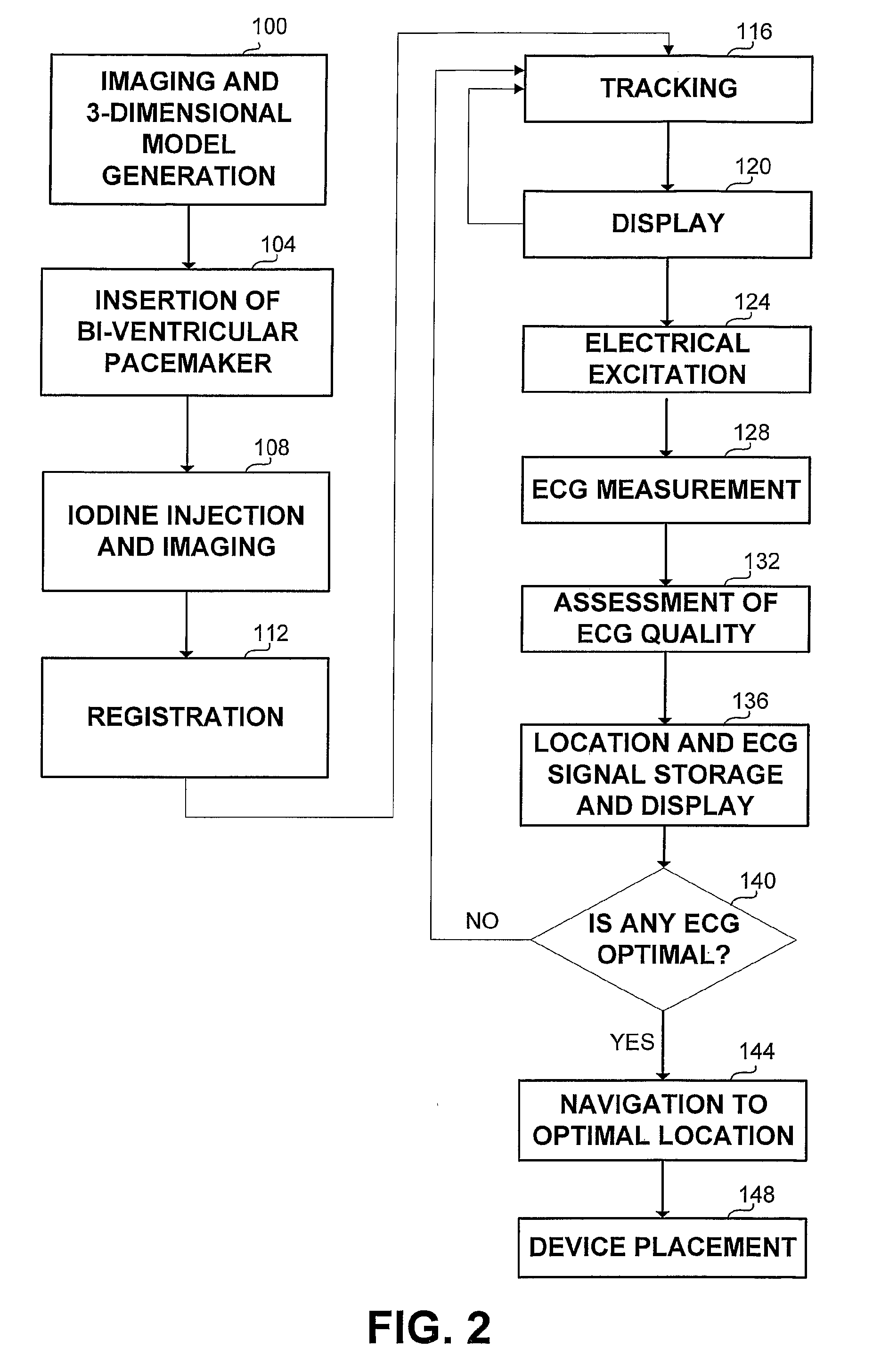
[0011]It is an object of the present invention to provide a novel method for determining a destination location position for a device within a body area of a patient, and navigating the device to the destination location. In accordance with the present invention, there is thus provided a method for determining a destination location for a device within a body area of a patient, the method comprising the steps of tracking the device within the body area using a model of the body area; at each of at least one location, obtaining one or more values of one or more parameters effected by the device, said values associated with said locations; storing the values and the associated locations; and determining a destination location associated with the values. The model can be a three-dimensional model, the body area can be the coronary venous system, the device can be an electrode of a bi-ventricular pacemaker and the parameter can be any of the group consisting of: electrocardiogram; heart rate; pulse; temperature; blood pressure and visual inspection. The method can further comprise the any if the steps of: generating the model of the body area, injecting the patient with contrast agent, assessing the quality of values of the parameters associated with the locations; presenting an image comprising elements from the model and the device to a user, navigating the device to the destination location, positioning the device at the destination location, activating the device in order to affect the values of the parameters. The method can further comprise the step of presenting to a user one or more locations in the body area together with the associated values of the parameters. The one or more locations can be presented on an image of the model, and can be marked on the image. The one or more locations can be presented to a user in a table. The step of locating the device within the model can comprise the steps of: obtaining an image of the device and the body area; and registrating the image with a model of the body area.
[0012]Another aspect of the present invention relates to an apparatus for determining a destination location for a device within a body area, the apparatus comprising

Problems solved by technology

Many people worldwide suffer from abnormal heart rhythm, where the rhythm may be too rapid, too slow, or irregular.
For most people, arrhythmias are harmless, but some arrhythmias have serious consequences, such as falls, motor vehicle accidents, heart failure and occasionally, sudden death.
Some problems such as premature atrial beats, supraventricular tachycardia, atrial flutter, and atrial fibrillation involve the upper chambers (atriums), other problems such as premature ventricular beats, ventricular tachycardia, and ventricular fibrillation result from problems in the lower chambers (ventricles).
Yet other types of arrhythmias result from problems in initiating and conducting electrical currents including malfunction of the heart block or the heart's pacemaker, such as some cases of sinus bradycardia and sick sinus syndrome.
Because of the blood flow within the venous system, from distal areas to proximal areas, the contrast material disperses too fast in the veins.
The above procedure suffers from non optimal pacemaker positioning.
Since it is difficult to navigate within the venous tree, which is different from patient to patient, and specifically, the interventionist might not be able to mark and return to a previously found location which yields better ECG response.

Method used


Image

  • Method and apparatus for positioning a biventrivular pacemaker lead and electrode
  • Method and apparatus for positioning a biventrivular pacemaker lead and electrode
  • Method and apparatus for positioning a biventrivular pacemaker lead and electrode

Examples


Embodiment Construction

[0017]The disclosed invention offers an apparatus and method that overcome the disadvantage of the existing lead implantation procedure. The invention provides a physician with means to position a lead of a bi-ventricular pacemaker, connected to the electrode that should be placed in the left ventricle, to an optimal location through the coronary venous system. The invention preferably uses a 3-dimensional model of the coronary venous system, as generated from at least two angiographs, taken form two different angles, either prior to or during the implantation procedure. Alternatively, the apparatus can use a 3-dimensional model acquired from an external source. Then, the biventricular pacer lead is inserted into the coronary venous system, and one or more injections of contrast agent, such as iodine, are performed, followed by taking additional angiograms. The contrast agent angiogram enables the registration of the 3-dimensional model with the current angiograms (including iodine ...


PUM


Abstract

An apparatus and method for placing a device in a body area of a patient, by: tracking the device over a 3-dimensional model of the body area; activating the device at different locations in the body area; measuring the response signal or parameter caused by the activation; storing the locations as well as the response signals; choosing an optimal location for the device base in the stored response signals and navigating the device to the optimal location.

Description

RELATED APPLICATIONS[0001]The present invention relates to international patent application titled “METHOD AND APPARATUS FOR POSITIONING A DEVICE IN A TUBULAR ORGAN” submitted on Mar. 31, 2005 and assigned to the same assignee as the present invention, which is a continuation in part of U.S. patent application Ser. No. 10 / 451,543 titled “METHOD AND APPARATUS FOR POSITIONING AN OBJECT IN AN ARTERY” filed on Jul. 24, 2003 with priority dated Oct. 18, 2000, and a continuation in part of European patent application designated serial number 1980855.9 titled “METHOD AND APPARATUS FOR POSITIONING AN OBJECT IN AN ARTERY” filed on 30 Jul. 2003 with priority dated 18 Oct. 2000, the contents of which are incorporated herein by reference.[0002]The present invention also relates to International patent application serial number PCT / IL01 / 00201 titled “SYSTEM AND METHOD FOR THREE-DIMENSIONAL RECONSTRUCTION OF AN ARTERY” filed on 2 Mar. 2001, the content of which is incorporated herein by reference...

Claims


Application Information

Patent Timeline
IPC IPC(8): A61B6/00A61N1/372
CPCA61B6/12A61B6/466A61N1/08A61B6/504A61B6/5235A61B6/481
Inventor ASSIS, TSURIELKLAIMAN, MOSHEZARKH, MICHAEL
Owner MEDTRONIC INC
Learn More