Image quantization and coding based on adaptive threshold

a threshold and adaptive threshold technology, applied in the field of image quantization and an apparatus for coding images, can solve the problems of increasing power consumption, prolonging and so as to prolong the time required for the process and increase power consumption. , the effect of affecting the value of the camera as a consumer produ

Inactive Publication Date: 2007-02-06
SANYO ELECTRIC CO LTD
View PDF10 Cites 6 Cited by
  • Summary
  • Abstract
  • Description
  • Claims
  • Application Information

AI Technical Summary

Benefits of technology

[0006]In the context of the above, the inventor of the present invention has considered the problem presented below. JPEG or other image compression technology is used when storing an image in a digital camera or the like. In this compression process, the image is subject to transform in order to be decomposed into a spatial frequency domain. The components in the spatial frequency domain are then quantized. The threshold for the quantization is fixed at the initial stage. The threshold must be adjusted and the quantization must be repeated when a desired compression ratio is not achieved. This trial and error process may prolong the time required for the process and increase power consumption, which may in turn affect the value of the camera as a consumer product.

Problems solved by technology

This trial and error process may prolong the time required for the process and increase power consumption, which may in turn affect the value of the camera as a consumer product.

Method used


Image

  • Image quantization and coding based on adaptive threshold
  • Image quantization and coding based on adaptive threshold
  • Image quantization and coding based on adaptive threshold

Examples


embodiment 1

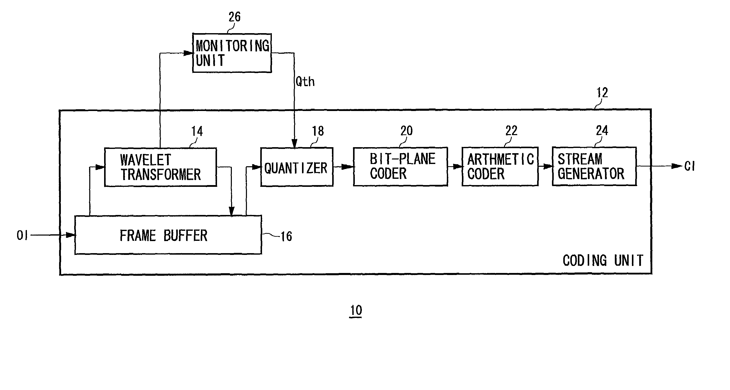
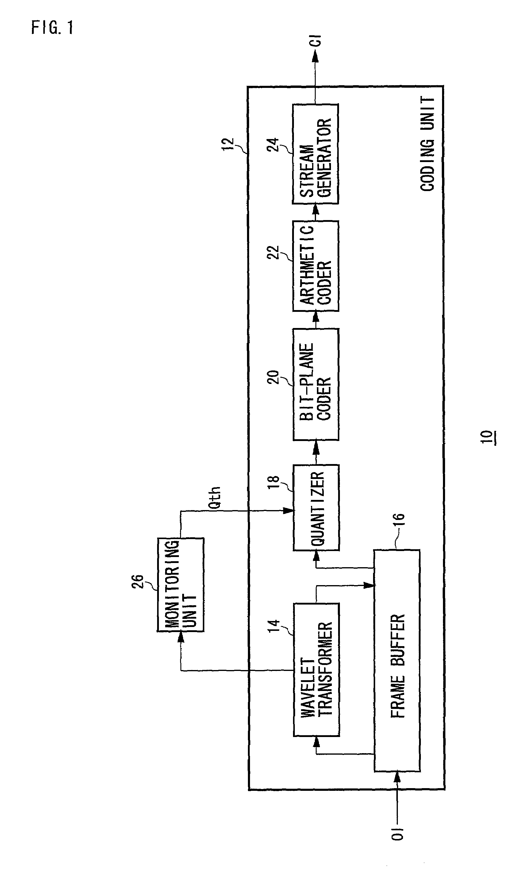
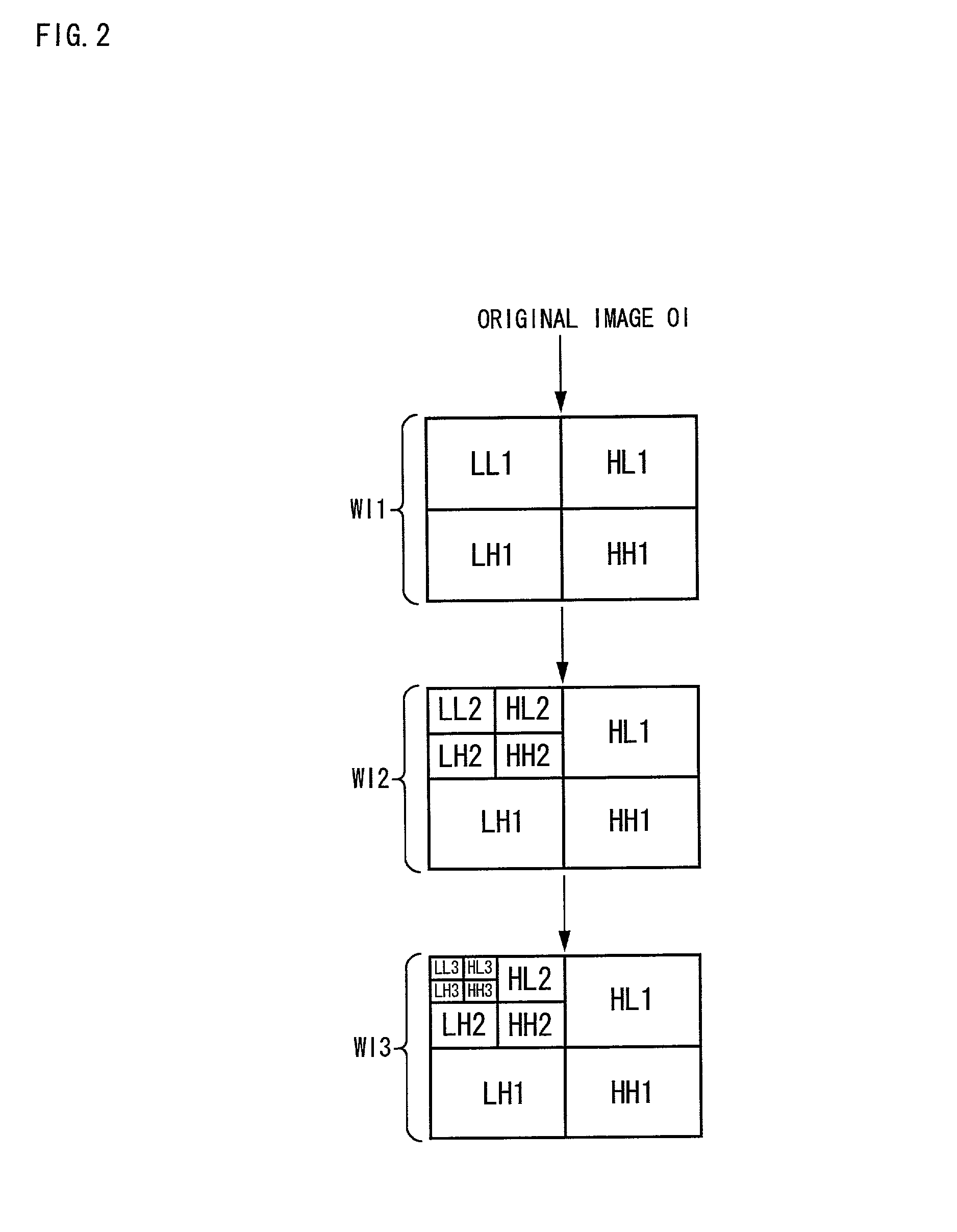
[0024]FIG. 1 shows the configuration of an image coding apparatus 10 according to Embodiment 1. FIG. 2 shows the process to make an image hierarchy by a wavelet transform which is conducted in one stage of image coding. The image coding apparatus 10 may be a normal computer and comprises a CPU, memory and program modules to code images loaded in the memory. The blocks in FIG. 1 depict functions characteristic of the present embodiment and those skilled in the art understand the functional blocks can be embodied as hardware only, software only or a combination of the two. Here, the entire coding process of JPEG 2000 is first explained, followed by the adaptive determination of a threshold value for the quantization process which is characteristic of the present embodiment.

[0025]The image coding apparatus 10 comprises a coding unit 12 and a monitoring unit 26. The coding unit 12, which works on the specifications of JPEG 2000, comprises a wavelet transformer 14, a frame buffer 16, a q...

embodiment 2

[0047]FIG. 6 shows the configuration of a digital camera 200 according to Embodiment 2. The digital camera 200 comprises a shooting block 202, a mechanism control block 204, a processing block 206, an LCD monitor 208 and operation buttons 210.

[0048]The shooting block 202 comprises a lens, a lens stop, an optical low-pass filter (LPF), a CCD and a signal processor (not shown). The CCD accumulates charge according to the amount of light received from an object imaged on the light receiving plane of the CCD. The charge is read as a voltage signal, which is decomposed into R, G and B components in the signal processor. The components are subject to white balance adjustment and gamma correction. The R, G and B signals are then input to an A / D converter from which digital image data are output to the processing block 206.

[0049]The mechanism control block 204 controls the optical system including zooming, focusing and iris of the shooting block 202. The processing block 206 comprises a CPU...


PUM


Abstract

A monitoring unit monitors continuously wavelet transform component output from a wavelet transformer. When a condition “make all the components of the HH sub-band 0” is applied as a quantization strategy, the monitoring unit detects the maximum value N among the components in the HH sub-band and determines the threshold as N+1. The threshold is then sent to a quantizer.

Description

BACKGROUND OF THE INVENTION[0001]1. Field of the Invention[0002]This invention relates to a technique for quantization of images. This invention especially relates to a method and apparatus for image quantization, and an apparatus for coding images using the quantization method.[0003]2. Description of the Related Art[0004]In recent years digital image culture has become commonplace in our daily life as various information devices such as personal computers, digital cameras and color printers have been introduced into our homes and the number of Internet users has exploded. Image compression technology such as JPEG (Joint Photographic Expert Group) and MPEG (Motion Picture Expert Group) for still images and motion images respectively has been standardized. Image distribution and reproduction have become easy and convenient for users using recording media such as CD-ROM and transmission media such as networks and broadcasting technology based on the aforementioned image compression te...

Claims


Application Information

Patent Timeline
Patent Type & Authority Patents(United States)
IPC IPC(8): G06K9/36G06T9/00H04N19/132H03M7/30H03M7/40H04N1/40H04N1/41H04N7/24H04N19/136H04N19/196H04N19/34H04N19/60H04N19/635H04N19/91
CPCH04N19/63H04N19/1883H04N19/124
Inventor OKADA, SHIGEYUKI
Owner SANYO ELECTRIC CO LTD
Why Eureka
Try Eureka