Steering assist system

a technology of steering assist and steering wheel, which is applied in the direction of anti-collision systems, non-deflectable wheel steering, underwater vessels, etc., can solve the problems of insecurity and discomfort of drivers, and achieve the effect of small lane width and natural feeling

Active Publication Date: 2009-08-27
SUBARU CORP
View PDF5 Cites 31 Cited by
  • Summary
  • Abstract
  • Description
  • Claims
  • Application Information

AI Technical Summary

Benefits of technology

[0016]In this case, when the preceding vehicle is within the range from the position the first distance apart inward from the right or left traffic line, to the position the second distance apart outward from the traffic line, a target traveling point is set at a position offset from the normal setting position toward the center of the traveling lane. Therefore, the range near the traffic line where the traveling target point is offset is made clear, and the advantage of the above-described advantage of the invention is achieved reliably.
[0017]Preferably, an offset amount of the traveling target point is set so that the absolute value of the offset amount increases as the preceding vehicle moves farther away from the center of the traveling lane of the subject vehicle.
[0018]In this case, the offset amount of the traveling target point is set so that the absolute value thereof increases as the preceding vehicle moves farther away from the center of the traveling lane of the subject vehicle. Therefore, in a condition in which the preceding vehicle is approaching from the center of the traveling lane toward one of the traffic lines, the subject vehicle can be caused to travel toward a side slightly shifted from the preceding vehicle toward the center of the traveling lane. In a condition in which the preceding vehicle is traveling over the traffic line or almost outside the traffic line, the subject vehicle can be caused to travel toward a side greatly shifted from the preceding vehicle toward the center of the traveling lane. For this reason, steering control for following the preceding vehicle can be naturally performed in a condition suited to the feeling of the driver without giving any feeling of insecurity and discomfort to the driver, and the above-described advantages of the invention can be achieved more effectively.
[0019]Preferably, an offset amount of the traveling target point is calculated according to the following expression when the preceding vehicle is traveling near the right traffic line:Ox=-11001300·dpl(r)-1100and the offset amount is calculated according to the following expression when the preceding vehicle is traveling near the left traffic line:Ox=-11001300·dpl(l)+1100where a right side in a width direction of the subject vehicle is a positive side, Ox represents the offset amount, and dpl(r) and dpl(l) respectively represent positions of the preceding vehicle relative to the right and left traffic lines in the width direction of the subject vehicle, and satisfy the following conditions:−1300≦dpl(r)≦1300−1300≦dpl(l)≦1300
[0020]In this case, the offset amount of the traveling target point is set according to the above-described expressions so that the absolute value of the offset amount increases in a linear function manner according to the position of the preceding vehicle relative to the traffic line. Therefore, control can be performed so that the subject vehicle can follow the preceding vehicle without running out of the traffic line while giving a more natural feeling to the driver, and the above-described advantages of the invention can be achieved more effectively.
[0021]Preferably, the traveling-target-point setting means sets the traveling target point at the predetermined position in the preceding vehicle without offsetting the traveling target point when it is determined that the preceding vehicle is within both the predetermined ranges from the detected right and left traffic lines.

Problems solved by technology

This gives the driver a feeling of insecurity.
This gives the driver a feeling of discomfort.

Method used


Image

  • Steering assist system
  • Steering assist system
  • Steering assist system

Examples


Embodiment Construction

[0061]A steering assist system according to an embodiment of the present invention will be described below with reference to the drawings.

[0062]While a preceding vehicle and traffic lines marked on the road are detected by analyzing stereo images taken by two cameras in the following description, the detection means is not limited to the cameras as long as it can detect the preceding vehicle and the traffic lines. For example, the preceding vehicle and so on can be detected by analyzing reflected waves of radio waves emitted from a radar apparatus, or can be detected by using a camera and a radar apparatus in combination.

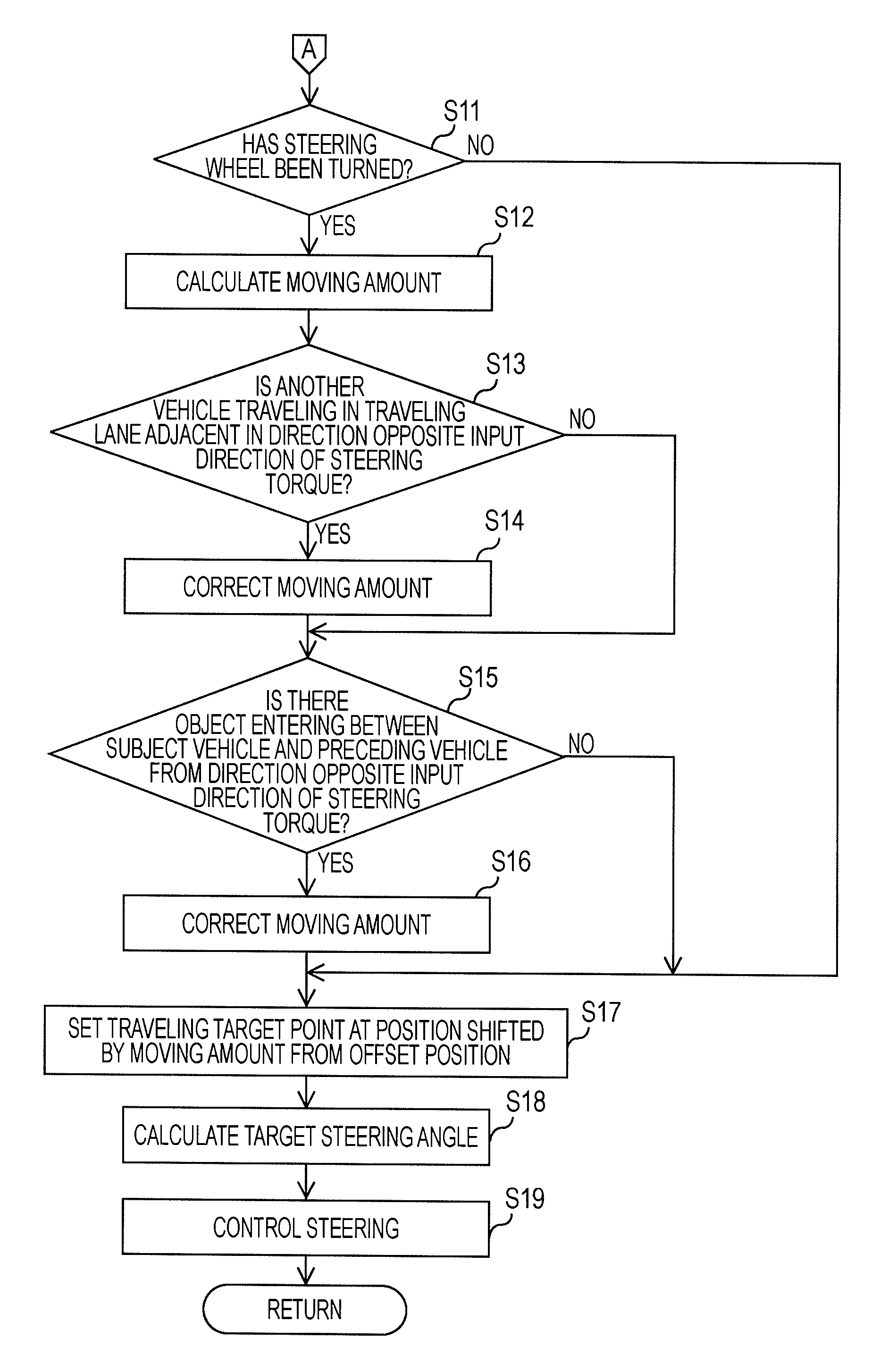
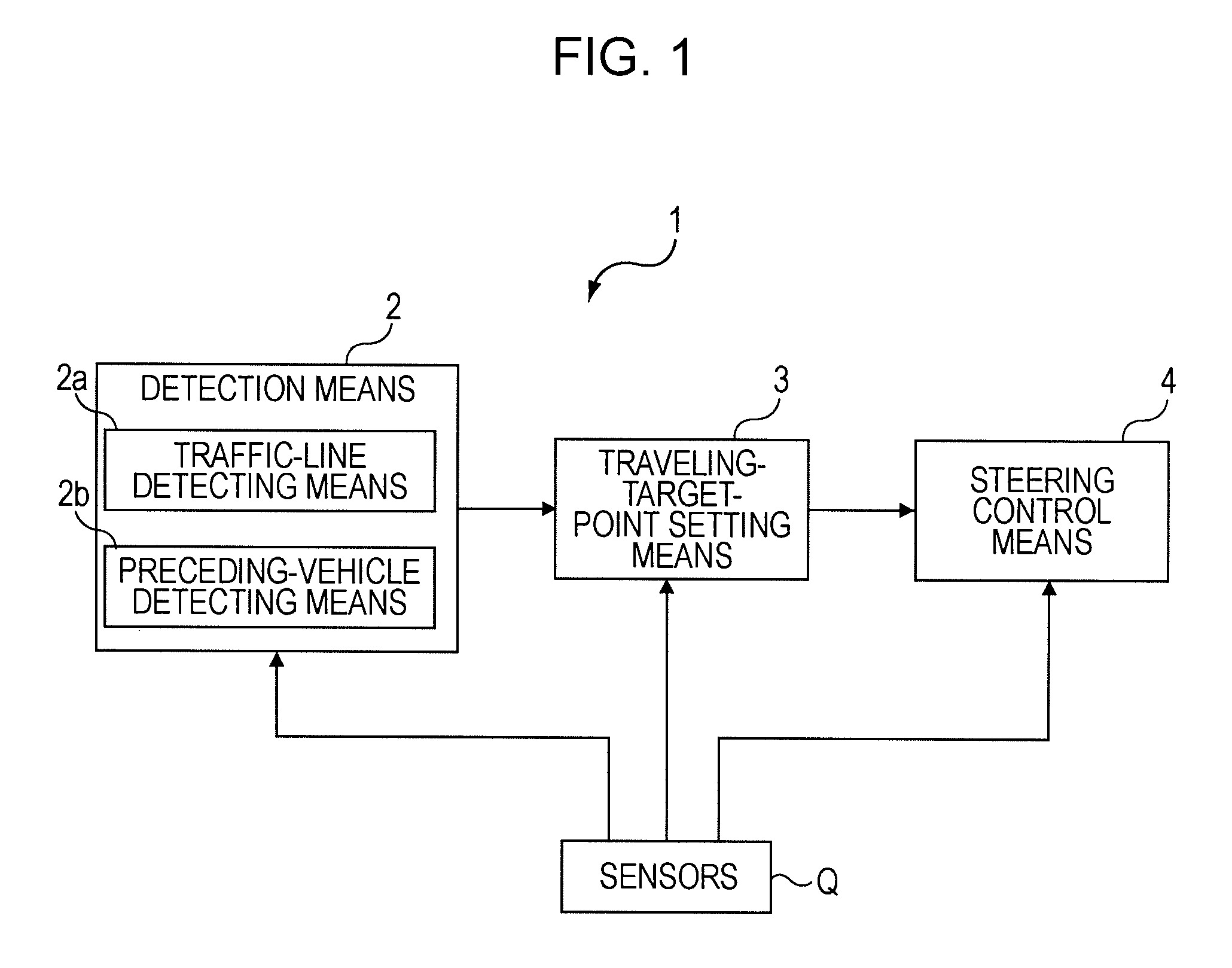
[0063]Referring to FIG. 1, a steering assist system 1 according to the embodiment includes a detection means 2 having a traffic-line detecting means 2a and a preceding-vehicle detecting means 2b, a traveling-target-point setting means 3, and a steering control means 4.

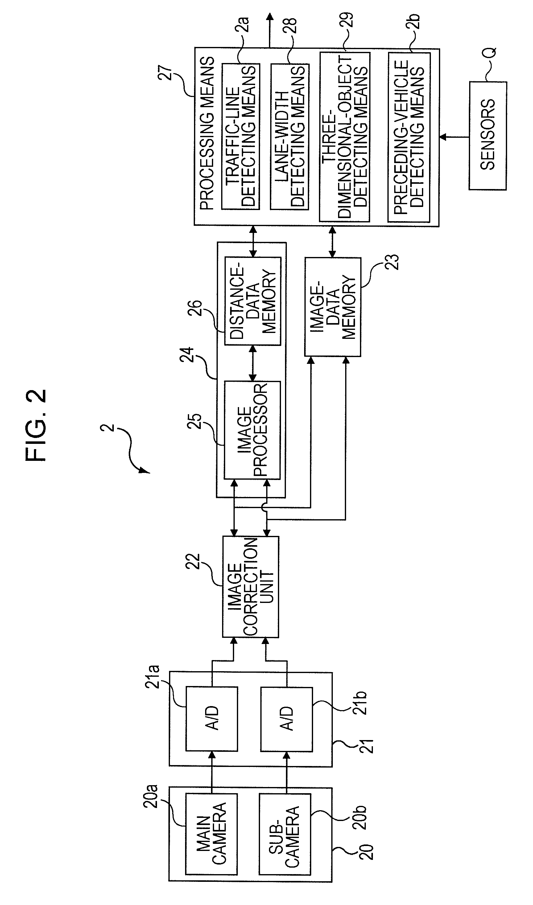
[0064]As shown in FIG. 2, the detection means 2 mainly includes an image taking means 20, a convers...


PUM


Abstract

A steering assist system includes traffic-line detecting means for detecting right and left traffic lines marked on a road, preceding-vehicle detecting means for detecting a preceding vehicle traveling ahead of a subject vehicle, traveling-target-point setting means for setting a traveling target point for traveling of the subject vehicle at a predetermined position in the preceding vehicle when the preceding vehicle is not within predetermined ranges from the right and left traffic lines, and for setting the traveling target point at a position offset from the predetermined position in the preceding vehicle toward the center of a traveling lane of the subject vehicle when the preceding vehicle is within the predetermined range of any one of the right and left traffic lines, and steering control means for controlling steering so that the subject vehicle passes over the traveling target point.

Description

CROSS-REFERENCE TO RELATED APPLICATIONS[0001]The disclosure of Japanese Patent Application No. 2008-046192 filed on Feb. 27, 2008 including the specification, drawings and abstract is incorporated herein by reference in its entirety.BACKGROUND OF THE INVENTION[0002]1. Field of the Invention[0003]The present invention relates to steering assist systems, and more particularly, to a steering assist system that controls steering so that a subject vehicle can follow a preceding vehicle.[0004]2. Description of the Related Art[0005]In recent years, steering assist systems have been developed. In steering assist systems, a preceding traveling ahead of a subject vehicle is detected by analyzing an image taken by an image taking means, such as a stereo camera, or analyzing reflected waves of radio waves emitted from a radar apparatus, and the steering angle and so on of the subject vehicle are automatically controlled so that the subject vehicle can follow the preceding vehicle (for example, ...

Claims


Application Information

Patent Timeline
Patent Type & Authority Applications(United States)
IPC IPC(8): B62D6/00
CPCB62D15/025H04N2013/0092
Inventor KUDO, SHINYA
Owner SUBARU CORP
Why Eureka
Try Eureka