Human Waste System

a waste and human waste technology, applied in water installations, construction, domestic plumbing, etc., can solve the problems of difficult draining and transportation of liquid and solid was

Inactive Publication Date: 2009-09-03
HALL DAVID R MR
View PDF12 Cites 4 Cited by
  • Summary
  • Abstract
  • Description
  • Claims
  • Application Information

AI Technical Summary

Problems solved by technology

In some situations it is very difficult to drain and transport liquid and solid waste.

Method used


Image

  • Human Waste System
  • Human Waste System
  • Human Waste System

Examples


Embodiment Construction

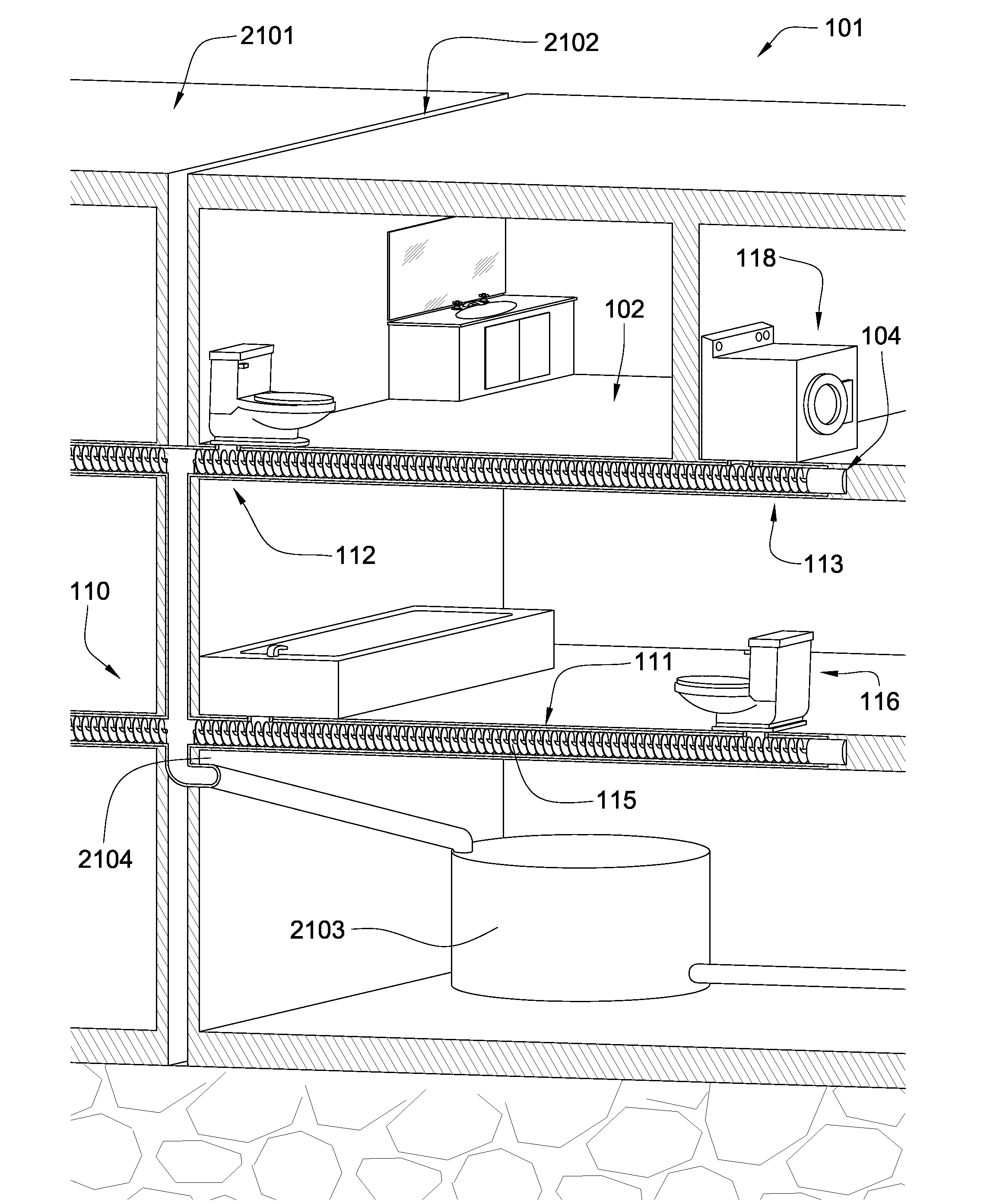
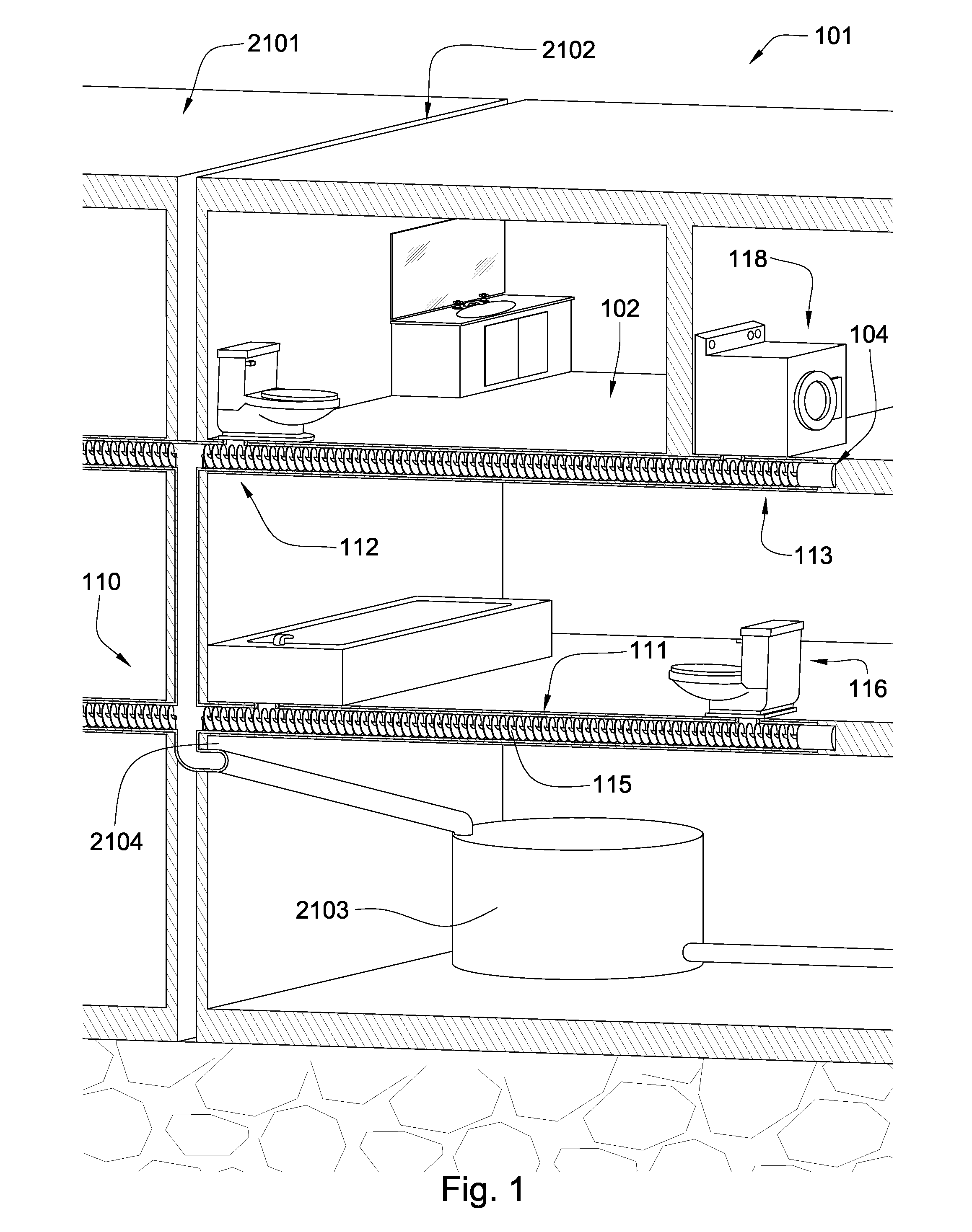
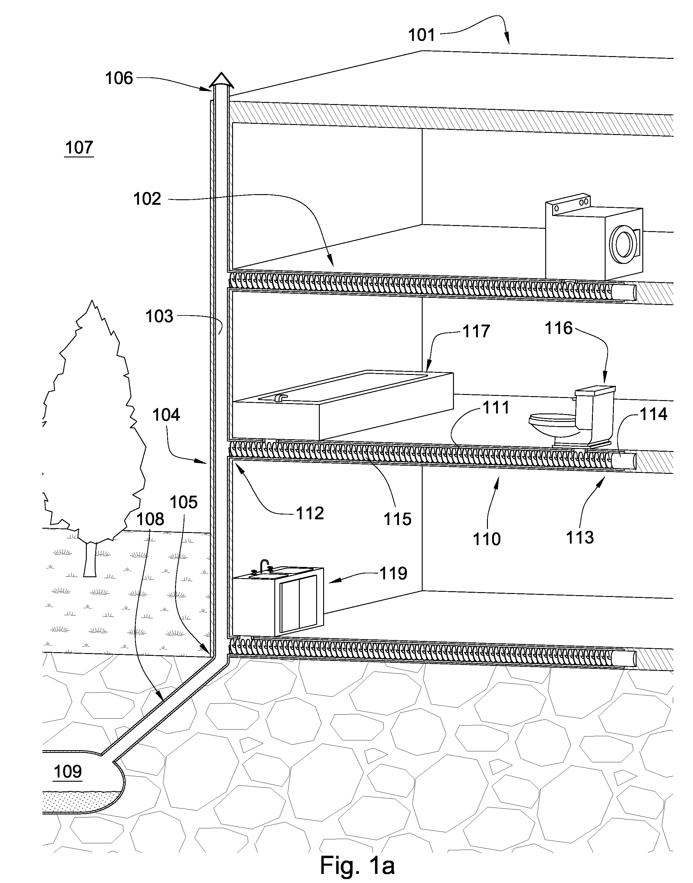
[0030]FIG. 1 is a diagram of an embodiment of the invention. A building 101 shares a sewer system 110 with an adjacent building 2101. Both buildings 101, 2101 are equipped with substantially horizontal pipes disposed within the floors and or ceilings and are in fluid communication with toilets 116, tubs, washing machines 118, dishwashers, sinks and other facilities that expel waste into the sewer system. An auger 115 in the horizontal pipes 111 moves sewage in a generally horizontal fashion within the floor from one end of the pipe to another end, where it is dumped into shared pipes 2104 located is a utility space 2102 between the buildings which direct the sewage to an anaerobic digester 2103. The anaerobic digester 2103 uses micro-organisms to break down the sewage and turn it into CO2, methane, and soil nutrients. Preferably the products of the anaerobic digester are re-used in the vicinity of the buildings such as in gardens or powering machines and vehicles. The auger 115 allo...


PUM


Abstract

In one aspect of the present invention, a system for the transportation of liquid and solid waste incorporated into a floor of a building has a generally horizontal pipe with a first and second end. A motor is disposed at the first end and an auger is disposed in and along at least a portion of a length of the pipe and is in communication with the motor. The auger is adapted to the transport of liquid and solid waste along the at least a portion of the length of the pipe.

Description

CROSS REFERENCE TO RELATED APPLICATIONS[0001]This application is a continuation of U.S. patent application Ser. No. 12 / 039,553, which was filed on Feb. 28, 2008 and entitled Sewer System.BACKGROUND OF THE INVENTION[0002]The current invention relates to sewer systems. In some situations it is very difficult to drain and transport liquid and solid waste. Consequently, many efforts have been made to develop a more effective way to drain and transport liquid and solid waste.[0003]U.S. Pat. No. 4,830,585 to Ruyle, which is herein incorporated by reference for all that it contains discloses a system for pumping a fluid of variable consistency into a fluid container. The system includes a vacuum power assist auger to withdraw fluid upwardly from a reservoir. A hose connecting an outlet end of the power assist auger to a fluid inlet at one end of a booster pump assembly is provided to supply fluid to the fluid inlet. A fluid outlet is provided at another end of the booster pump assembly. Th...

Claims


Application Information

Patent Timeline
Patent Type & Authority Applications(United States)
IPC IPC(8): E03D11/00
CPCE03C1/122
Inventor HALL, DAVID R.LEANY, FRANCISWILDE, TYSON J.BLACK, BOYD
Owner HALL DAVID R MR
Why Eureka
Try Eureka