Splatter indicator sight for firearms

Inactive Publication Date: 2009-09-03
9609385 CANADA INC
View PDF21 Cites 22 Cited by
  • Summary
  • Abstract
  • Description
  • Claims
  • Application Information

AI Technical Summary

Benefits of technology

[0006]The object of the present invention is to provide firearms with a splatter indicator sight which will take many important variables affecting the bullet trajectory into consideration to create a risk zone map of the different zones which can be hit after the use

Problems solved by technology

Despite these existing sighting systems, aiming errors still occur.
The aiming error becomes a considerable issue when the firearm is used by security forces in civilian zones where there ex

Method used


Image

  • Splatter indicator sight for firearms
  • Splatter indicator sight for firearms
  • Splatter indicator sight for firearms

Examples


Embodiment Construction

[0022]The present invention is illustrated in further details by the following non-limiting examples.

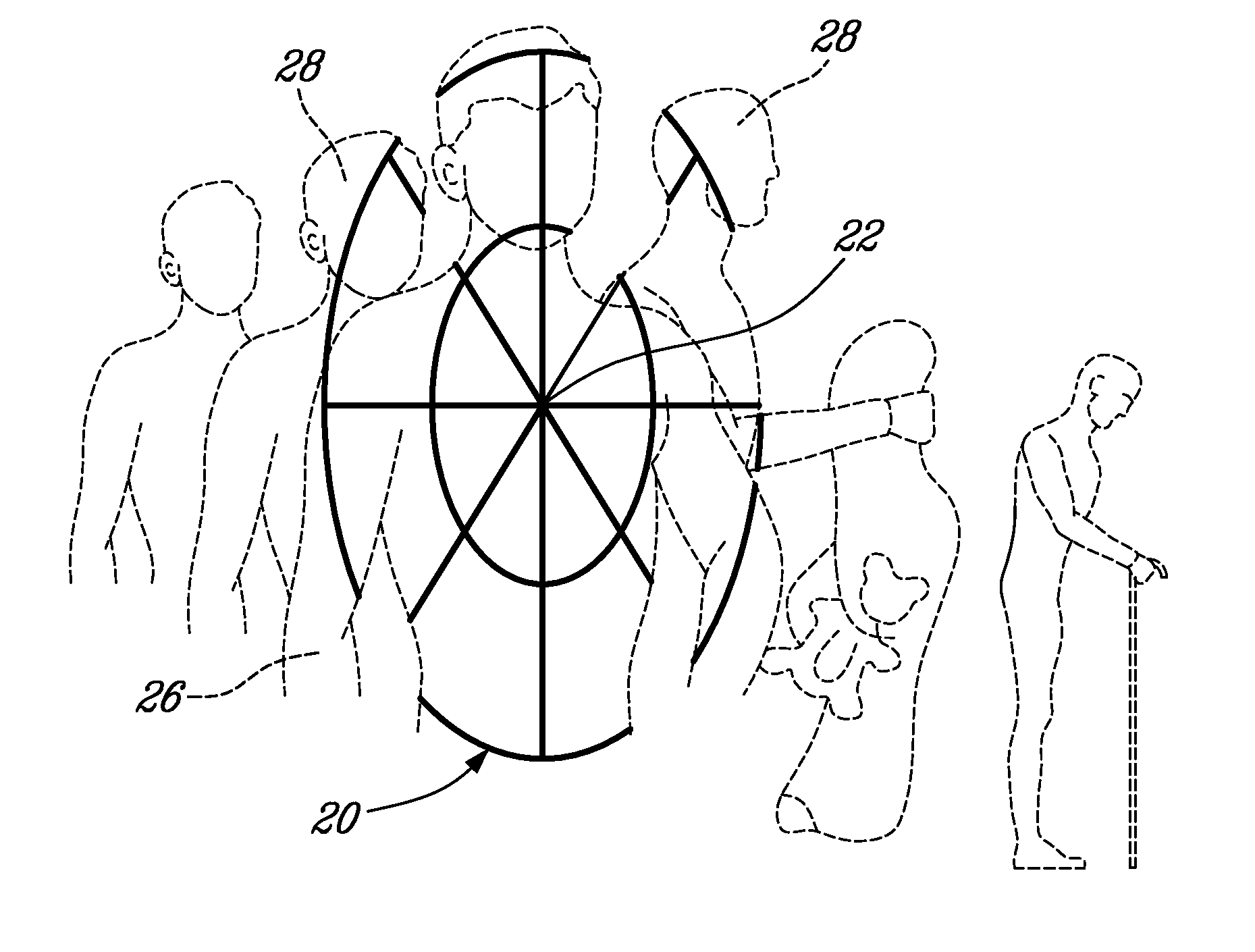
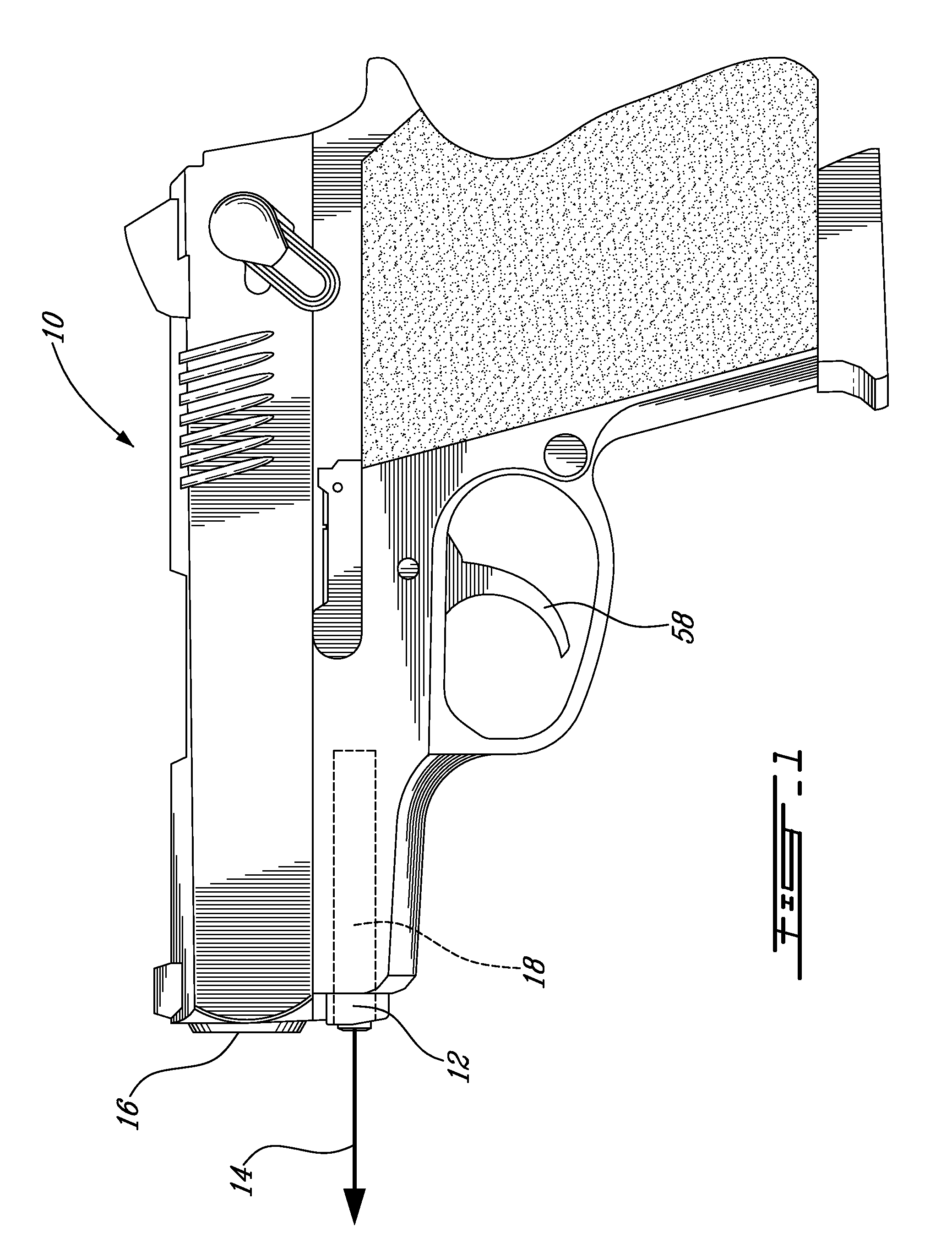
[0023]Referring now to FIG. 1, and in accordance with an illustrative embodiment of the present invention, a firearm comprising a splatter indicator sight, and generally referred to using the reference numeral 10, will now be described. The firearm 10 comprises a splatter indicator sight 12 comprising a laser (not shown) emitting a laser beam 14 co-aligned with the muzzle 16. The indicator sight 12 is illustratively mounted within the chamber 18 which also houses the recoil spring (not shown). Alternatively, the indicator sight 12 could be positioned on top of a firearm 10 or below the barrel on a dovetail, MIL-STD-1913 Picatinny rail or similar mount.

[0024]Still referring to FIG. 1, many aiming errors are directly caused by the user. For example, parallax is created when the user moves in relation to the sight 12. Additionally, normal shaking of the hand holding the firearm 10 can b...


PUM


Abstract

A splatter indicator sight for use with a firearm taking one or more variables affecting the bullet trajectory under consideration to create a risk zone map of the different zones which can be hit after the user has aimed the firearm at a target. In embodiments of the invention, the boundaries of the most probable hit zones can be quickly indicated to the user by the risk zone map. The risk zone map is illustratively created by projecting a laser beam directly on the target.

Description

CROSS REFERENCE TO RELATED APPLICATIONS[0001]This application claims priority, under 35 U.S.C. § 119(e), of U.S. provisional application Ser. No. 61 / 020,515, filed on Jan. 11, 2008 and is incorporated herein in its entirety by reference.FIELD OF THE INVENTION[0002]The present invention relates to a splatter indicator sight for firearms. More specifically, the present invention is concerned with an indicator device for processing data regarding variables affecting the bullet trajectory and creating a visual map of all of the probable hit zones after the user has aimed the firearm at the target, thereby allowing the user to evaluate the risk of hitting the wrong target before shooting.BACKGROUND OF THE INVENTION[0003]Firearms, such as handguns (single-shot pistols, revolvers, and semi-automatic pistols), long guns (rifles, carbines or shotguns) and machine guns or the like are aimed at their targets with greater accuracy by using sights. Many sights can be mounted onto firearms, for e...

Claims


Application Information

Patent Timeline
IPC IPC(8): F41G1/00
CPCF41A17/08F41G1/473F41G1/35
Inventor FORD, TIMOTHY D.F.
Owner 9609385 CANADA INC
Why Eureka
Try Eureka