Metallic floor box with non-metalic riser and flange

a floor box and non-metal technology, applied in the field of floor boxes, can solve the problems that the curtain with the locknut cannot be achieved on the rectangular or planar surface, and achieve the effect of improving the clearance of wires, blending with building lines easier, and more aesthetically pleasing

Active Publication Date: 2009-09-03
HUBBELL INC
View PDF25 Cites 19 Cited by
  • Summary
  • Abstract
  • Description
  • Claims
  • Application Information

AI Technical Summary

Benefits of technology

[0009]First reason increased volume to rectangular housing for improved wire clearances and bend radius within housing. Second reason is EMT conduit with locknut can only be achieved on rectangular housing or planar surface. This product provides the benefits of a rectangular shape in the floor and then transitions to a round finished surface fitting. The round surface fitting is preferred because it blends with building lines easier and is more aesthetically pleasing. The transition from square housing to round cover is believed to be unique to this product.
[0010]According to one aspect of the device, a rectangular metallic floor box is attached to a cylindrical non-metallic riser having an integral flange which attaches to the top of the floor box. The rectangular shape of the box provides for increased wiring clearance and bend radius within the box. Further, EMT conduit with a locknut can easily interface with the planar surface of the rectangular box. The riser transitions from a rectangular flange which attaches to the rectangular box to a cylindrical riser which is completed with a round surface fitting at the floor surface. According to at least one embodiment of the invention, a round surface fitting is desired because it blends with building lines easier and is more aesthetically pleasing than other shapes. It is the transition from rectangular floor box housing to round cover that is believed to be one unique feature of a floor box consistent with the present invention.
[0011]Either electrical power devices, electrical data devices, or both, are connected within the floor box to cabling that enters the box via conduit connected to holes in one or more sides of the box. After the floor box is positioned within the floor at the desired location a cap is placed over the top of the riser and concrete is poured over the box and over the flange to the minimum depth of pour of the riser. The cap on top of the riser prevents concrete from spilling into the riser and into the electrical box. After the concrete settles and cures, the riser is cut flush with the hardened concrete floor and the desired sub-plate is installed to the finish flange, which houses the desired power and / or data distribution devices within the box. A selected cover plate is then installed over the sub-plate providing a convenient threshold between the floor, e.g., carpet, hardwood, etc., and the electrical outlet. The cover doors also provide protection to the installed devices when not in use. The cover doors may be secured independently of one another, allowing the user to access some or all of the services located beneath.
[0012]Another feature of the Hubbell device is an integral partition located on the riser below the flange. The integral partition eliminates the need for any additional parts for separating the data communications and power cabling within the floor box. Also, the riser with the integral partition can be used with both metallic and non-metallic floor boxes and can also be used with different depth boxes.
[0013]One aspect of the present invention is to provide a floor-box device with flexibility to create personal solutions for the most demanding multi-service applications for flush in-floor boxes. More particularly, a wide variety of application sub-plates can be installed on the floor-box to provide the desired flexibility. The truly unique feature of the product is that the application sub-plates, finish flanges and cover plates can be installed on either the Hubbell SystemOne metal floor box (described herein), the non-metallic floor box and or fire rated poke through. Thus simplifying the overall installation, procurement and specification of the devices.

Problems solved by technology

Second reason is EMT conduit with locknut can only be achieved on rectangular housing or planar surface.

Method used


Image

  • Metallic floor box with non-metalic riser and flange
  • Metallic floor box with non-metalic riser and flange
  • Metallic floor box with non-metalic riser and flange

Examples


Embodiment Construction

[0024]Exemplary, non-limiting, embodiments of the present invention are discussed in detail below. While specific configurations and dimensions are discussed to provide a clear understanding, it should be understood that the disclosed dimensions and configurations are provided for illustration purposes only. A person skilled in the relevant art will recognize that other dimensions and configurations may be used without departing from the spirit and scope of the invention.

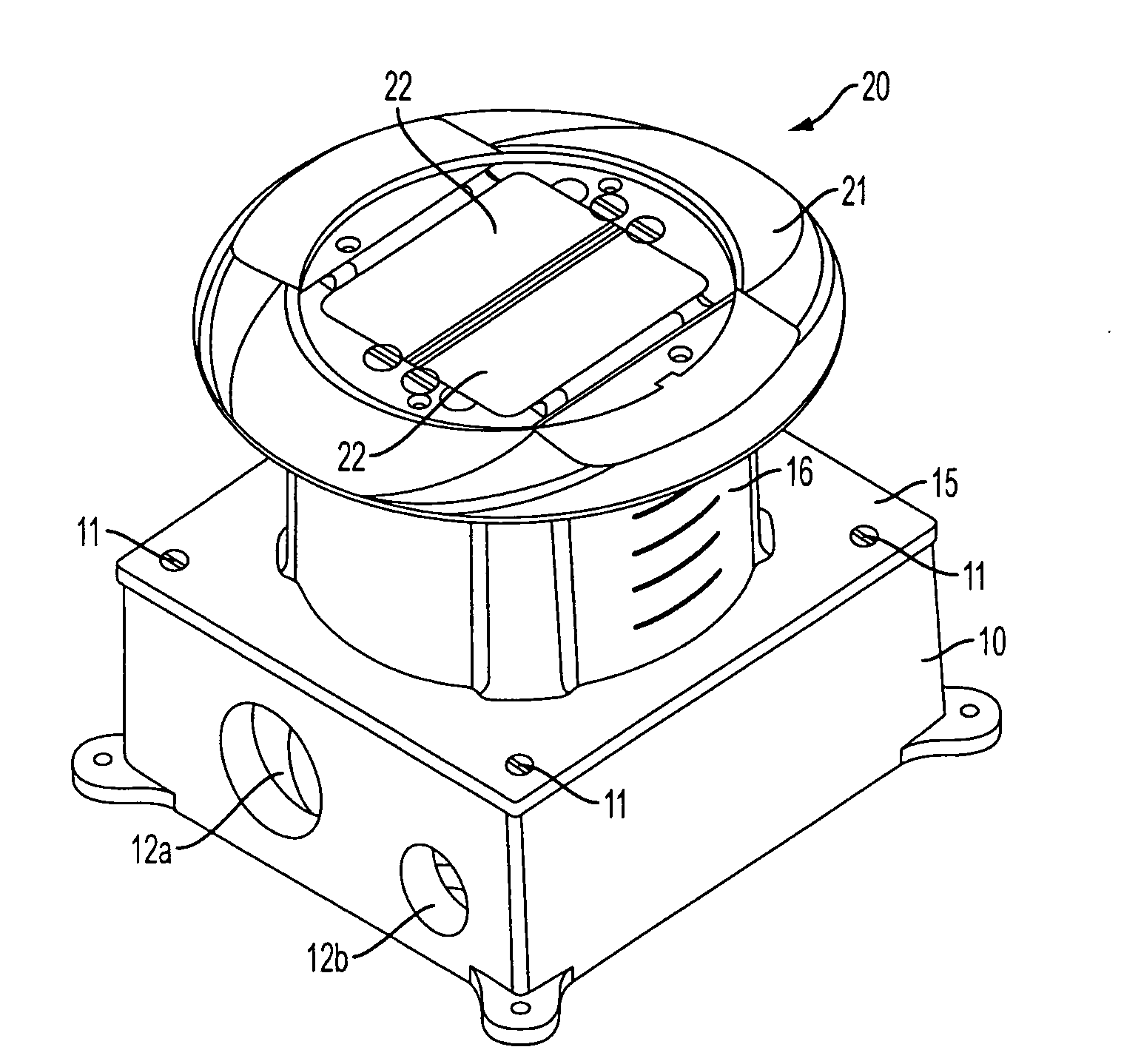
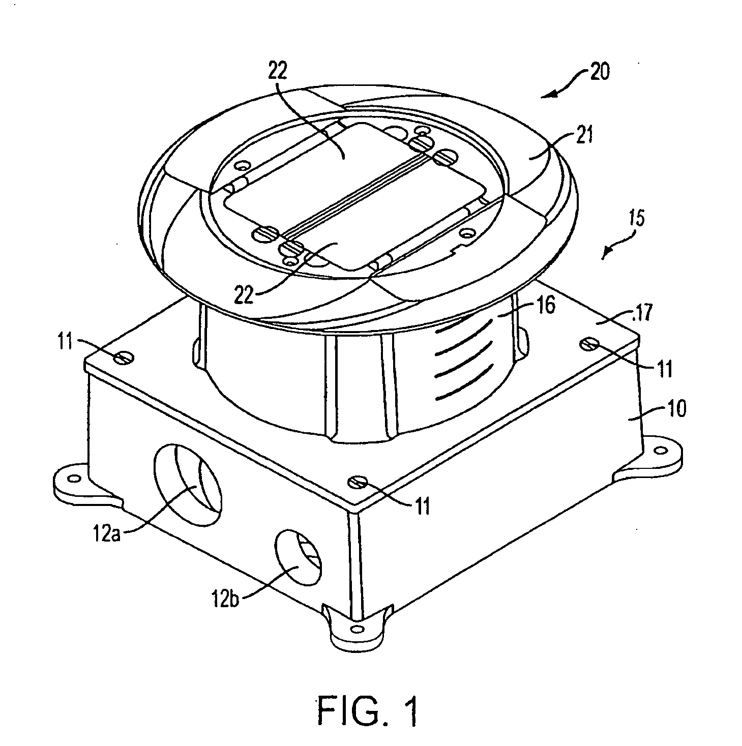
[0025]FIG. 1 illustrates an exemplary embodiment of the invention. In particular, the embodiment of FIG. 1 includes a rectangular metallic floor box 10 with a non-metallic riser with integral flange assembly 15 secured to a top thereof. Further, riser with integral flange assembly 15 comprises an integral riser 16 and is secured to the metallic floor box 10 using fasteners 11. According to the embodiment disclosed in FIG. 1 fasteners 11 are screws, however, one of ordinary skill would understand that other types of ...


PUM


Abstract

An in-floor electrical floor-box assembly includes a rectangular or nearly square metallic housing and a non-metallic riser with integral flange assembly having a rectangular flange that mates with the rectangular housing and an integral cylindrical riser for providing access to the electrical components through a round cover and finish flange. A low-voltage divider assembly separates cables carrying different voltages within the riser to reduce interference between the cables and any one of a variety of sub-plates having different configurations for accommodating a variety of multi-service or single service electrical functionality can be incorporated with the box.

Description

FIELD OF THE INVENTION[0001]This invention relates generally to a floor box for housing electrical power and / or low voltage (data, multi-media, A / V & communications) devices. More particularly, the device relates to a floor box for accommodating electrical power and data distribution devices within a floor.BACKGROUND OF THE INVENTION[0002]The invention relates in general to electrical in-floor power and communications distribution systems for commercial buildings and the like, and in particular to a metallic floor box with a non-metallic riser that accommodates varying floor material depths and multiple services.[0003]Conventional electrical floor boxes are problematic when used in connection with poured floors, such as concrete floors. One particular type of problem arises because the overall height of the floor box is typically fixed and, thus, if the final height of the poured floor is less than the height of the floor box, the floor box will protrude from the floor. Alternativel...

Claims


Application Information

Patent Timeline
Patent Type & Authority Applications(United States)
IPC IPC(8): H02G3/12H02G3/08
CPCH02G3/0493Y10S248/906H02G3/18H02G3/185
Inventor CARBONE, CHRISTOPHER A.DRECHSLER, DALE A.SCANZILLO, THOMAS L.
Owner HUBBELL INC
Why Eureka
Try Eureka