Sewer System
- Summary
- Abstract
- Description
- Claims
- Application Information
AI Technical Summary
Problems solved by technology
Method used
Image

Examples
Embodiment Construction
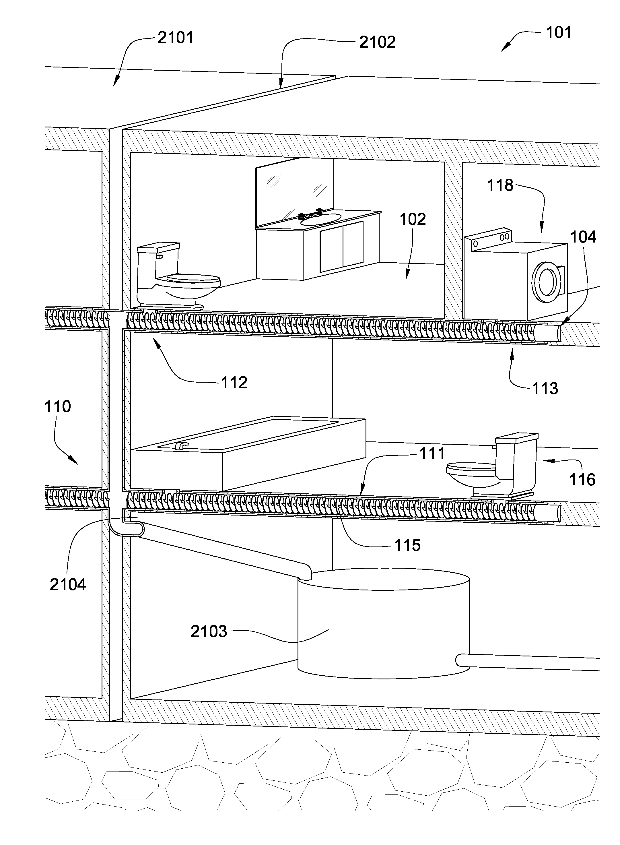
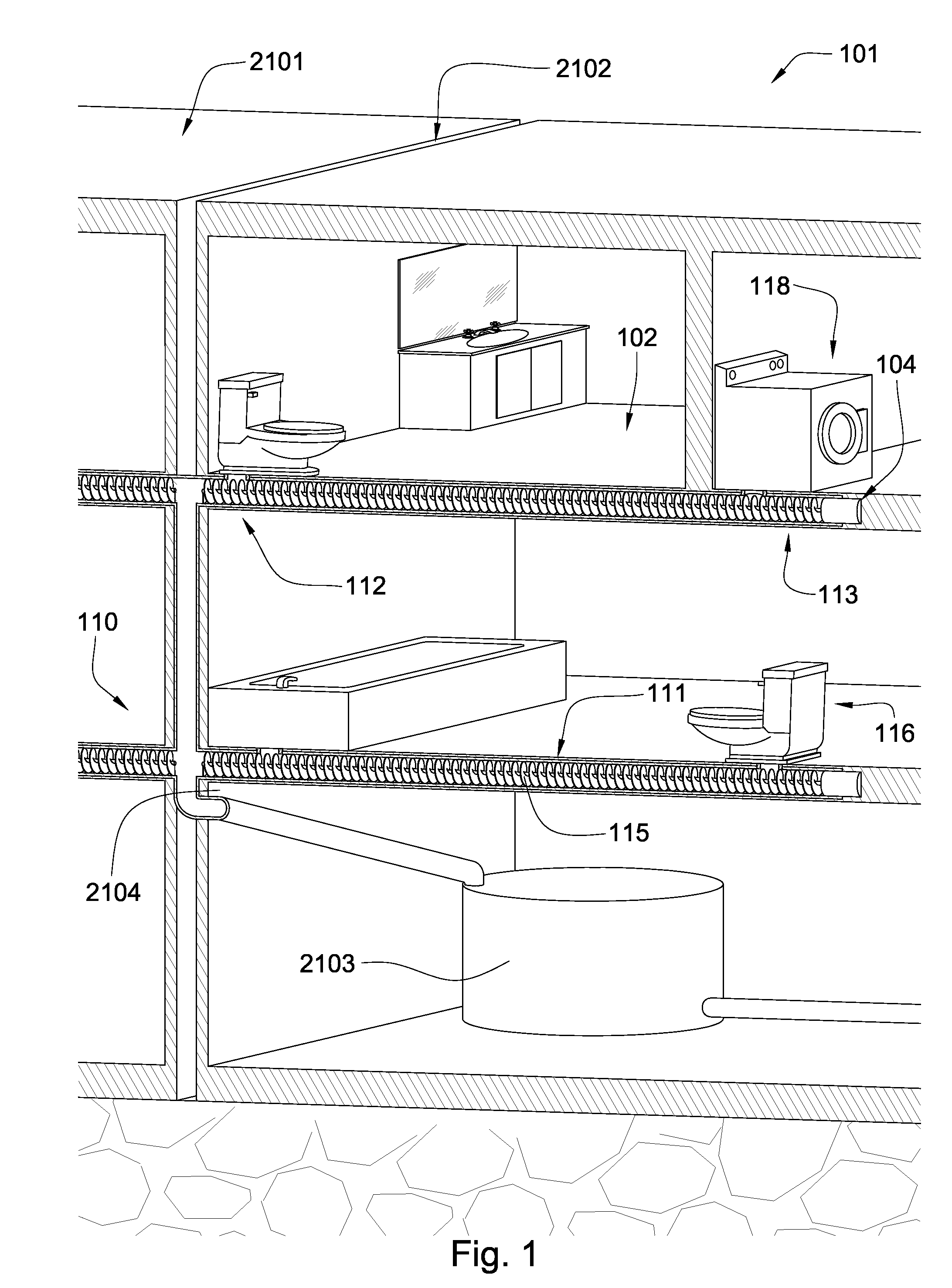
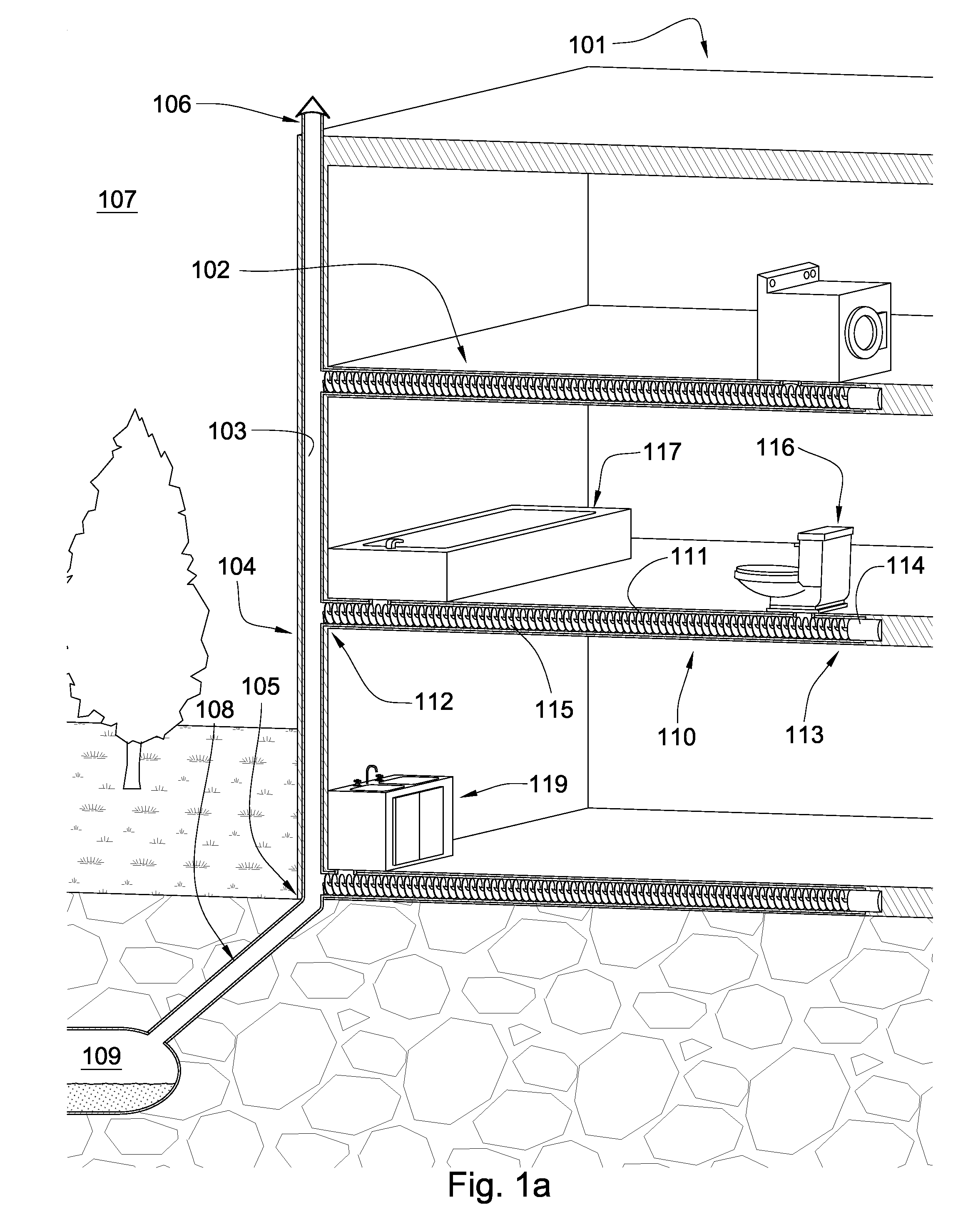
[0029]FIG. 1 is a diagram of an embodiment of the invention. A building 101 shares a sewer system 110 with an adjacent building 2101. Both buildings 101, 2101 are equipped with substantially horizontal pipes disposed within the floors and or ceilings and are in fluid communication with toilets 116, tubs, washing machines 118, dishwashers, sinks and other facilities that expel waste into the sewer system. An auger 115 in the horizontal pipes 111 moves sewage in a generally horizontal fashion within the floor from one end of the pipe to another end, where it is dumped into shared pipes 2104 located is a utility space 2102 between the buildings which direct the sewage to an anaerobic digester 2103. The anaerobic digester 2103 uses micro-organisms to break down the sewage and turn it into CO2, methane, and soil nutrients. Preferably the products of the anaerobic digester are re-used in the vicinity of the buildings such as in gardens or powering machines and vehicles. The auger 115 allo...
PUM
| Property | Measurement | Unit |
|---|---|---|
| Length | aaaaa | aaaaa |
| Torque | aaaaa | aaaaa |
Abstract
Description
Claims
Application Information